Method for automatically extracting center of out-of-focus blurred centering image of aspheric optical element

A technology of optical components and defocus blur, applied in image enhancement, image analysis, image data processing, etc., can solve problems such as defocus blur and difficulty in extracting the center

Active Publication Date: 2019-11-08
ZHEJIANG UNIV
View PDF11 Cites 7 Cited by
  • Summary
  • Abstract
  • Description
  • Claims
  • Application Information

AI Technical Summary

Problems solved by technology

[0003] The purpose of the present invention is to solve the problem that the centering reticle image of the rotationally symmetrical aspheric optical element is defocused and blurred due to the aberration of the aspheric normal line being greater than the depth of field of the system, so that it is difficult to extract the center

Method used


Image

  • Method for automatically extracting center of out-of-focus blurred centering image of aspheric optical element
  • Method for automatically extracting center of out-of-focus blurred centering image of aspheric optical element
  • Method for automatically extracting center of out-of-focus blurred centering image of aspheric optical element

Examples


Embodiment 1

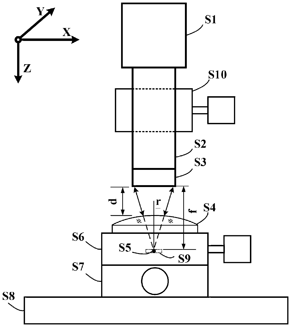
[0080] figure 1Shown is the structure diagram of the centering system, the Y-axis (S7) is placed on the marble platform (S8), the replacement objective lens (S3), the CCD (S1) and the centering instrument (S2) are connected by threads. When initializing, first control the X-axis (S6) and Y-axis (S7) to run the rotationally symmetrical aspheric element (S4) directly below the replacement objective lens (S3), and then adjust the Z-axis (S10) so that the replacement objective lens (S3) and the rotation The distance d between the symmetrical aspheric optical elements (S4) is equal to the focal length f of the replacement objective lens (S3). At this time, the image on the upper surface of the cross reticle through the rotationally symmetrical aspheric optical element (S4) can be obtained, and then according to the rotation The spherical radius r of the vertex of the symmetrical aspheric optical element (S4) (positive when the convex surface faces up, and negative when the concave ...


PUM


Abstract

The invention discloses a method for automatically extracting a center of an out-of-focus blurred centering image of an aspheric optical element. The method includes: taking a gray variance definitionevaluation function as a measurement standard, and obtaining a region of interest with the highest definition in a coarse focusing image, namely a region where the center of a cross reticle is located; selecting the image with the highest SMD2 value of the ROI from the odd number of images acquired at equal step pitch; if the value is smaller than a prior threshold value, performing deblurring processing on the optimally focused image by using a trained IRCNN deep learning model or based on an improved dark channel prior algorithm, then obtaining a connected domain of the cross reticle by using adaptive threshold binaryzation and morphological operation, and solving a maximum inscribed circle of the connected domain, the circle center of the inscribed circle being approximate to the center of the cross reticle. According to the invention, the problem that the center of the centering cross reticle image of the aspheric optical element is difficult to extract due to defocusing blurringcaused by the fact that the aspheric normal aberration is greater than the depth of field of the system is solved.

Description

technical field [0001] The invention belongs to the technical field of machine vision detection, and in particular relates to a method for automatically extracting a center of a defocused blurred centering image applied to a rotationally symmetrical aspheric optical element. Background technique [0002] Aspherical optical components are widely used in large-aperture space telescopes, inertial confinement fusion (ICF), high-energy lasers and other systems. Due to uncontrollable forces in the manufacturing process, there will inevitably be defects on the surface of the components. These defects will not only affect The imaging quality of the optical system will also produce unnecessary scattering and diffraction in the high-energy laser system, which will cause energy loss and may cause secondary damage. Therefore, it is necessary to detect and evaluate surface defects. The aspheric element is centered so that its optical axis is as collinear as possible with the optical axis...

Claims


Application Information

Patent Timeline
Patent Type & Authority Applications(China)
IPC IPC(8): G06T7/62G06K9/32
CPCG06T7/62G06T2207/10004G06T2207/20081G06T2207/20084G06V10/25
Inventor 杨甬英王凡祎楼伟民白剑
Owner ZHEJIANG UNIV
Why Eureka
Try Eureka