
Energy-saving power distribution cabinet

A technology for power distribution cabinets and cabinets, which is applied to the substation/power distribution device shell, electrical components, substation/switch layout details, etc., which can solve the problems of excessive dust inhalation, reduced service life, high energy consumption, etc., and achieve increased The effect of contact area, accelerated heat dissipation, and improved service life

Active Publication Date: 2019-11-08
JIANGSU WELL ELECTRIC
View PDF5 Cites 5 Cited by
  • Summary
  • Abstract
  • Description
  • Claims
  • Application Information

AI Technical Summary

Problems solved by technology

[0004] In order to make up for the deficiencies of the existing technology, when the power distribution cabinet works in a mine with a tropical rainforest climate, due to the high air humidity, the electrical components in the power distribution cabinet are prone to moisture failure or short circuit, and excessive dust will be sucked in through the cooling fan. The electrical components in the power distribution cabinet are easy to short-circuit and reduce the service life; there are also some refrigeration equipment installed on the inner wall of the power distribution cabinet. Although the refrigeration device can reduce the temperature, the high-power refrigeration equipment continues to refrigerate, and the energy consumption is high. problem, the present invention proposes an energy-saving power distribution cabinet

Method used


Image

  • Energy-saving power distribution cabinet
  • Energy-saving power distribution cabinet
  • Energy-saving power distribution cabinet

Examples


Embodiment approach

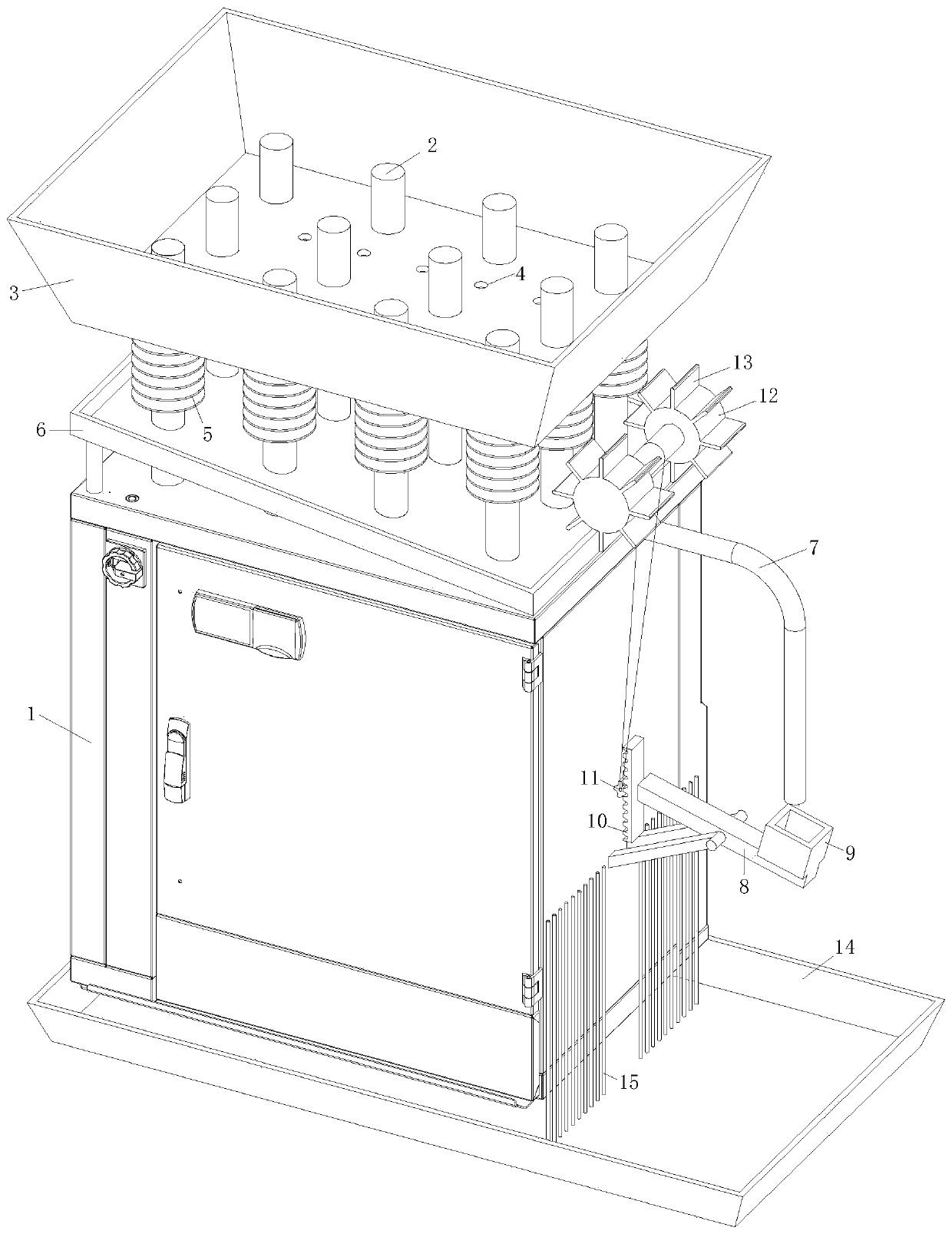
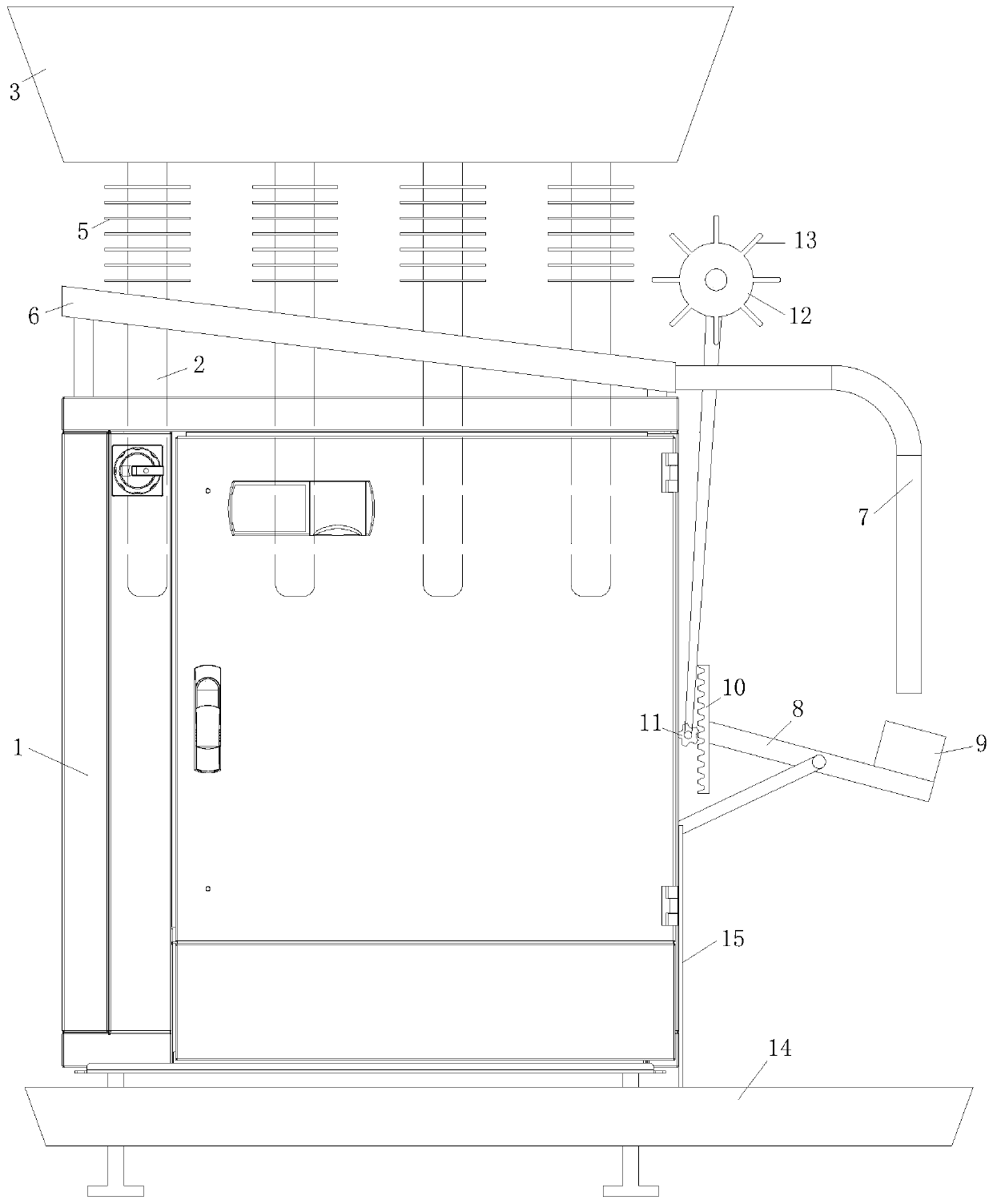
[0022] As an embodiment of the present invention, a group of shower holes 4 are evenly opened at the bottom of the reservoir 3, and the diameter of the shower holes 4 is 0.3 millimeters; the heat conduction between the cabinet body 1 and the reservoir 3 A set of cooling fins 5 is set on the tube 2; through the mutual cooperation between the water spray hole 4 and the cooling fins 5, the cooling speed of the cabinet body 1 is further accelerated to ensure the normal operation of the cabinet body 1; through the cooling fins 5, the heat pipe can be enlarged 2 and the contact area with the air, so as to accelerate the heat dissipation speed of the heat pipe 2, the rainwater stored in the reservoir 3 slowly drips onto the heat sink 5 through the water shower hole 4, and the water evaporates and absorbs heat on the heat sink 5, further The temperature of the heat sink 5 is lowered, thereby further accelerating the heat dissipation speed of the cabinet 1, and ensuring the normal opera...


PUM


Abstract

The invention belongs to the technical field of a power distribution cabinet, and specifically relates to an energy-saving power distribution cabinet, which comprises a, heat-conducting pipes and a water storage tank. The water storage tank with a top opening is fixedly arranged on the cabinet body through a support; a cabinet door of the cabinet body is sealed to the cabinet body through a sealing strip; the top portion of the cabinet body is uniformly provided with a group of hollow heat-conducting pipes made of red copper; each heat-conducting pipe is filled with ethyl alcohol, which accounts for one third of the volume of the hollow part of the heat-conducting pipe; the bottom ends of the heat-conducting pipes run through the top portion of the cabinet body and go into the cabinet body; and the top ends of the heat-conducting pipes run through the bottom portion of the water storage tank and are soaked in water. By absorbing the heat in the cabinet body through the heat-conductingpipes, the ethyl alcohol forms ethanol vapor; and the ethanol vapor rises to the top end of the heat-conducting pipe and then, is liquefied, and the heat is transferred to the rainwater stored in thewater storage tank, thereby achieving a purpose of cooling the cabinet body, making an electric appliance at normal operating temperature and improving service life of the electric appliance.

Description

technical field [0001] The invention belongs to the technical field of power distribution cabinets, in particular to an energy-saving power distribution cabinet. Background technique [0002] The power distribution cabinet (box) is divided into power distribution cabinet (box), lighting distribution cabinet (box), metering cabinet (box), and is the final equipment of the power distribution system. The power distribution cabinet is a general term for the motor control center. The power distribution cabinet is used in the occasions where the load is relatively scattered and there are few circuits; the motor control center is used in the occasions where the load is concentrated and there are many circuits. They distribute the electric energy of a certain circuit of the upper-level power distribution equipment to the nearest load. This level of equipment shall provide protection, monitoring and control of the load. [0003] When the current power distribution cabinet is in us...

Claims


Application Information

Patent Timeline
IPC IPC(8): H02B1/30H02B1/56
CPCH02B1/30H02B1/565
Inventor 童浩峥陈涛李涵
Owner JIANGSU WELL ELECTRIC
Learn More