Distributed DC microgrid control method

A DC microgrid and control method technology, applied in the field of electrical engineering, can solve problems such as heavy communication burden, and achieve the effect of maintaining control performance

Active Publication Date: 2019-11-08
HUAZHONG UNIV OF SCI & TECH
View PDF1 Cites 6 Cited by
  • Summary
  • Abstract
  • Description
  • Claims
  • Application Information

AI Technical Summary

Problems solved by technology

[0005] The invention provides a distributed DC micro-grid control method, which is used to solve the technical problem of excessive communication burden caused by using a parallel structure to control power and voltage in the existing distributed DC micro-grid control method

Method used


Image

  • Distributed DC microgrid control method
  • Distributed DC microgrid control method
  • Distributed DC microgrid control method

Examples


Embodiment 1

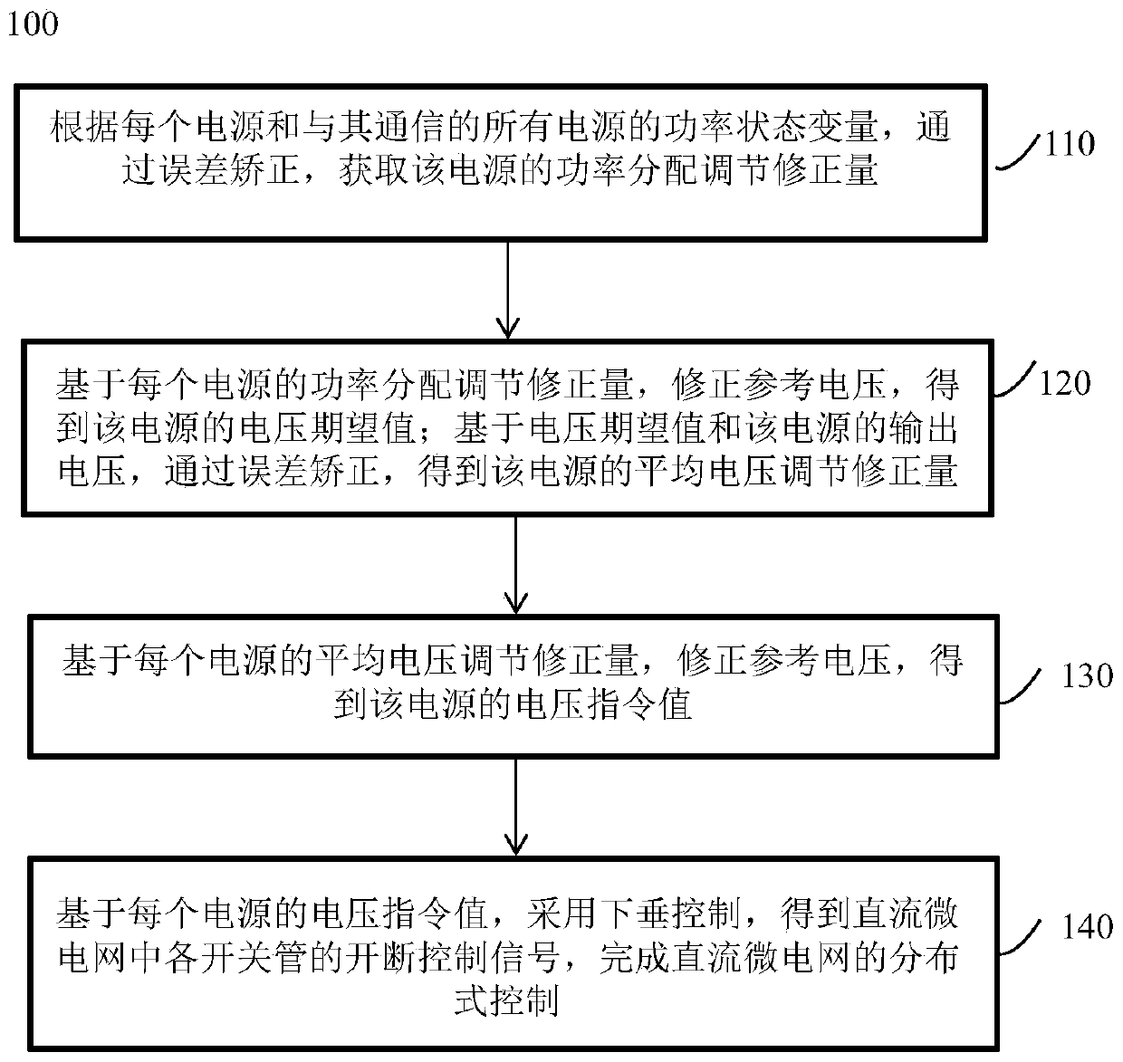
[0046] A distributed DC microgrid control method 100, such as figure 1 shown, including:

[0047] Step 110, according to the power state variables of each power supply and all power supplies communicating with it, through error correction, obtain the power distribution adjustment correction value of the power supply;

[0048] Step 120: Based on the power distribution adjustment correction amount of each power supply, correct the reference voltage to obtain the expected voltage value of the power supply; based on the expected voltage value and the output voltage of the power supply, obtain the average voltage adjustment correction amount of the power supply through error correction;

[0049] Step 130, adjusting the correction amount based on the average voltage of each power supply, correcting the reference voltage, and obtaining the voltage command value of the power supply;

[0050] Step 140, based on the voltage command value of each power supply, adopt droop control to obt...

Embodiment 2

[0086] A storage medium, in which instructions are stored, and when a computer reads the instructions, the computer is made to execute any one of the distributed DC microgrid control methods described in Embodiment 1.

[0087] For example, a cascaded distributed computer control system suitable for DC microgrids includes a primary control unit and a secondary control unit. The primary control unit adopts a traditional droop controller, including a droop module, an inner loop voltage control module, an inner loop current control module and a PWM signal generator; the secondary control unit includes a power regulation module and a voltage control module.

[0088] Among them, the droop module is used to obtain the input signal of the inner loop voltage control module (inner loop control output voltage expected value) according to the set virtual droop coefficient, voltage command value and output power value; the inner loop voltage control module is used to obtain the input signal...


PUM


Abstract

The invention discloses a distributed DC microgrid control method. The distributed DC microgrid control method comprises the steps of: obtaining, according to a power state variable of each power source and all power sources communicating with the power source, the power distribution and regulation and correction amount of the power source through error correction; based on the correction amount,correcting a reference voltage to obtain a voltage expected value; based on a voltage expected value and an output voltage, performing error correction to obtain the average voltage regulation and correction amount of the power source; based on the correction amount, correcting the reference voltage to obtain a voltage instruction value; and based on the voltage instruction value of each power source, adopting the droop control to obtain the cut-off control signal of each switch tube in the DC microgrid. The power distribution regulation and correction amount and the average voltage regulationand correction amount are sneaked into the correction of the reference voltage one by one to eliminate the inherent voltage and power distribution deviation of the primary droop control to achieve the power and voltage control of the DC microgrid so as to reduce the communication amount required by the operation of the distributed controller while maintaining the control performance and reduce the communication burden.

Description

technical field [0001] The invention belongs to the field of electrical engineering, and more specifically relates to a distributed DC microgrid control method. Background technique [0002] DC microgrid, because it gets rid of the common frequency, phase and reactive power problems of AC microgrid, has the potential to achieve more stable and efficient operation with a simpler control structure, and has attracted extensive attention from the academic community. And with the widespread access of renewable energy and the increase of DC loads in recent years, the advantages of DC microgrids are further reflected. In a DC microgrid, random fluctuations and uncertainties of renewable energy sources and loads will cause power imbalance in the system and deteriorate the stability of the system. The energy storage unit is usually applied to supply the load demand and dynamically compensate the unbalanced power of the system to maintain a constant bus voltage. Reasonable power dis...

Claims


Application Information

Patent Timeline
Patent Type & Authority Applications(China)
IPC IPC(8): H02J1/10
CPCH02J1/10
Inventor 陈霞周建宇石梦璇闫林芳文劲宇
Owner HUAZHONG UNIV OF SCI & TECH
Why Eureka
Try Eureka