Eureka AIR delivers breakthrough ideas for toughest innovation challenges, trusted by R&D personnel around the world.

Abutting ejection device

A technology of ejecting device and tightening, applied in the field of machinery, can solve problems such as easy occurrence of jamming, unreasonable structural design, unfavorable grasping, assembly or processing, etc., to prevent deformation and material damage, ejection and sliding smoothly, The effect of reducing the cost of land use

Pending Publication Date: 2019-11-12
SUZHOU RS TECH
View PDF0 Cites 0 Cited by
  • Summary
  • Abstract
  • Description
  • Claims
  • Application Information

AI Technical Summary

Problems solved by technology

[0002] In the field of machinery such as non-standard automated assembly lines, it is often necessary to use a jacking and ejecting device that first tightens the material box containing the material, and then performs operations such as grabbing the material, assembling components, and processing the material. The existing jacking The ejection device has the following problems: First, it is easy to deflect the material box or material during the jacking process, which is not conducive to the subsequent accurate grasping, assembly or processing operations; secondly, due to the high jacking force during the jacking process Large or short jacking process, it is easy to cause a large impact on the material box and materials, resulting in deformation of the material box, material damage and other problems; thirdly, the structure is complex and not compact, and it takes up a lot of space, which is not convenient for centralized operations; Finally, the unreasonable structural design makes the material prone to jamming during the ejection process and the sliding process, resulting in low ejection efficiency

Method used

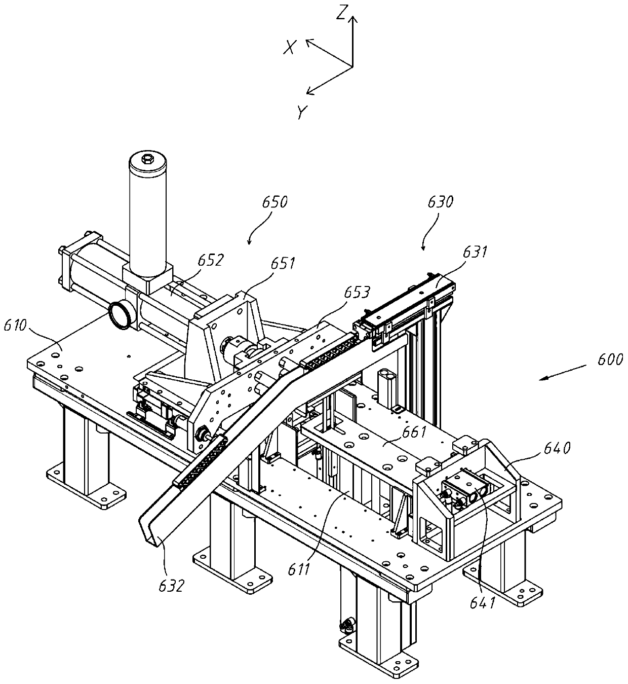
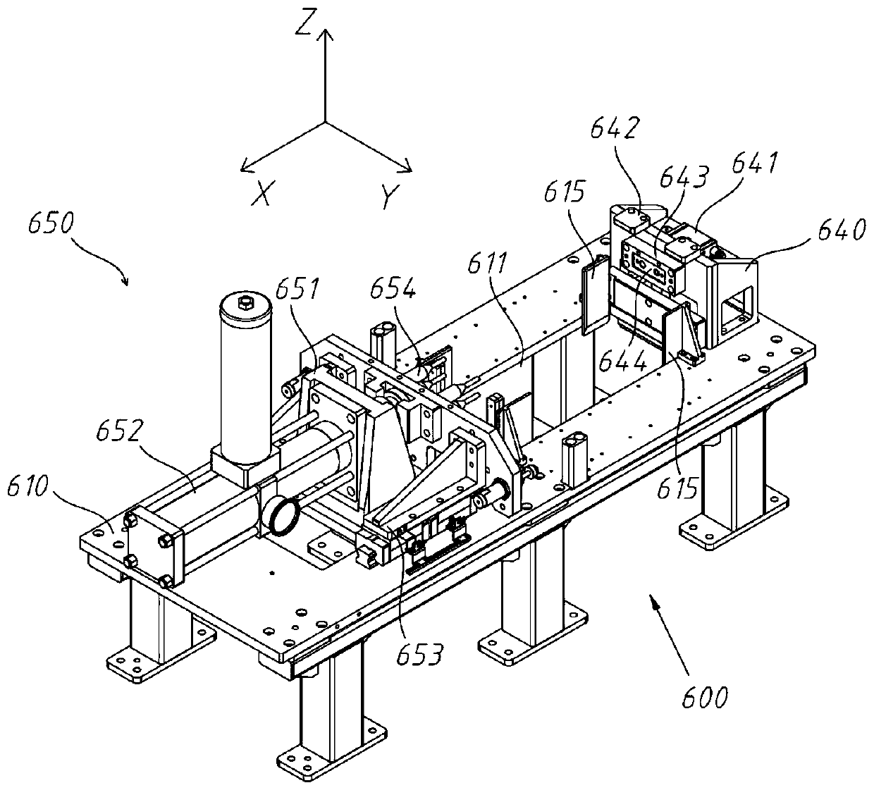
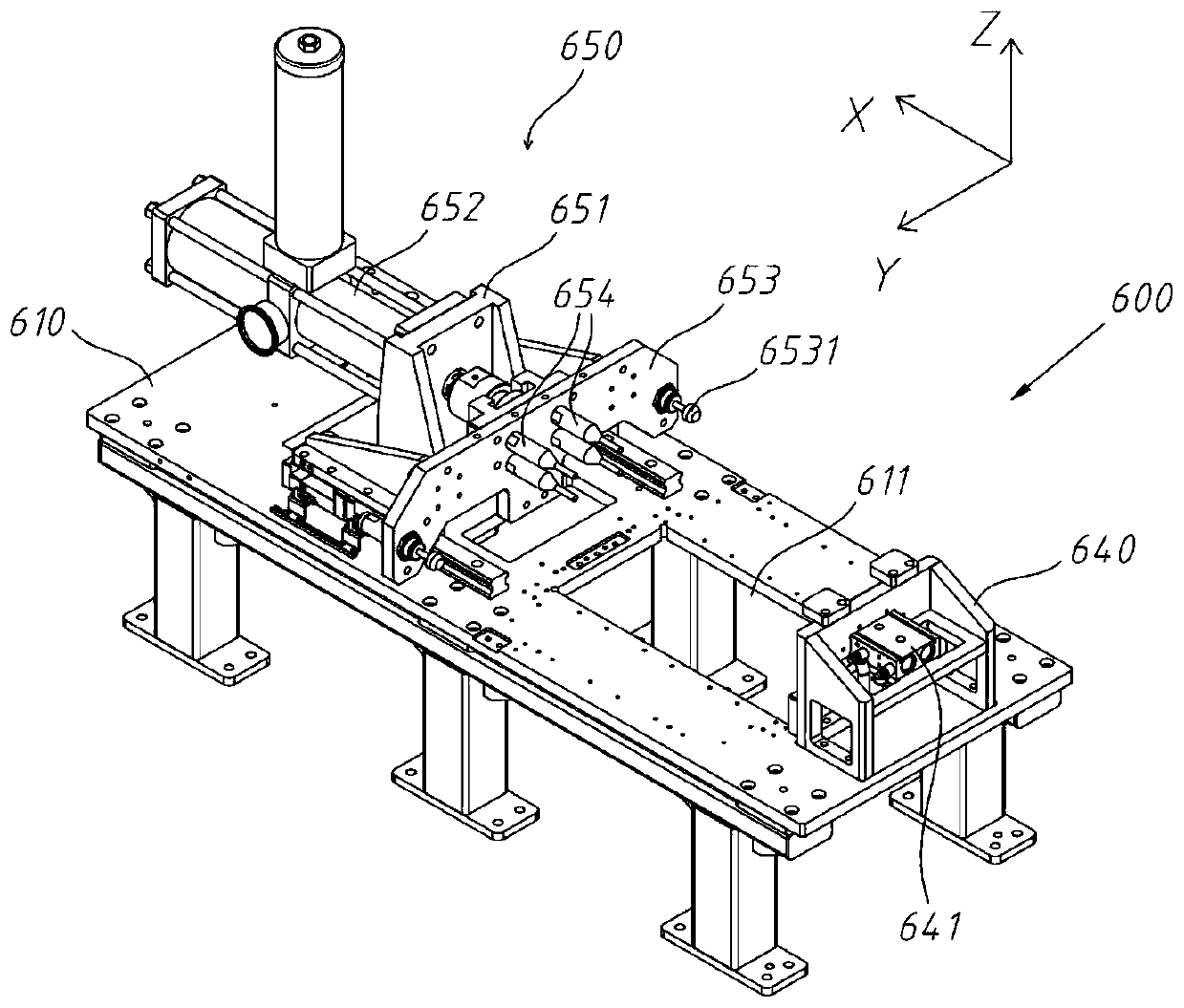

Image

  • Abutting ejection device
  • Abutting ejection device
  • Abutting ejection device

Examples


Embodiment Construction

[0039] The present invention will be further described in detail below in conjunction with the accompanying drawings, and the aforementioned and other objects, features, aspects and advantages of the present invention will become more apparent, so that those skilled in the art can implement them with reference to the description.

[0040] In the drawings, the shapes and dimensions may be exaggerated for clarity, and the same reference numerals will be used throughout to designate the same or like parts.

[0041] In the following description, terms such as center, thickness, height, length, front, back, rear, left, right, top, bottom, upper, lower, etc. are defined with respect to the configuration shown in each drawing , in particular, "height" is equivalent to the dimension from top to bottom, "width" is equivalent to the dimension from left to right, and "depth" is equivalent to the dimension from front to back. They are relative concepts, so it may be based on It changes co...


PUM


Abstract

The invention discloses an abutting ejection device. The device comprises a reference platform provided with a jacking through groove penetrating through the upper and lower surfaces of the referenceplatform, a jacking platform arranged at the position directly below the jacking through groove, a jacking driver for driving the jacking platform to reciprocally go up and down, a reference machine frame and an abutting assembly, wherein the reference machine frame and the abutting assembly are arranged on the outer circumference of the jacking through groove; the jacking platform is provided with an ejection block accommodating groove; an ejection block is accommodated in the ejection block accommodating groove; the ejection block is in drive connection with an ejection driver; and a guidingmechanism is arranged directly above the ejection block accommodating groove. According to the abutting ejection device, abutting force is prevented from deviating by arranging an abutting rod on anabutting template, subsequent operations such as accurate grasping, assembling or processing are facilitated, deformation of material boxes and material damage can be reduced, loss is reduced, the enterprise profits are increased, the abutting ejection device is compact in structure and small in floor space, and ejection and sliding of materials are smooth while the material boxes are jacked stably.

Description

technical field [0001] The invention relates to the mechanical field, in particular to a jacking and ejecting device. Background technique [0002] In the field of machinery such as non-standard automated assembly lines, it is often necessary to use a jacking and ejecting device that first tightens the material box containing the material, and then performs operations such as grabbing the material, assembling components, and processing the material. The existing jacking The ejection device has the following problems: First, it is easy to deflect the material box or material during the jacking process, which is not conducive to the subsequent accurate grasping, assembly or processing operations; secondly, due to the high jacking force during the jacking process Large or short jacking process, it is easy to cause a large impact on the material box and materials, resulting in deformation of the material box, material damage and other problems; thirdly, the structure is complex ...

Claims


Application Information

Patent Timeline
IPC IPC(8): B65G47/22B65G47/74
CPCB65G47/22B65G47/74
Inventor 吴加富缪磊马伟冯小平杜高峰
Owner SUZHOU RS TECH
Why Eureka
Eureka Blog
Learn More