Multi-station pneumatic reversing valve

A reversing valve and multi-station technology, applied in the direction of multi-way valves, valve details, valve devices, etc., can solve problems such as the expansion energy of compressed gas is not effectively utilized, the energy of compressed gas is wasted, and the energy of compressed air is wasted. It achieves the effects of multiple positions in the reversing working state, reducing impact at the end of the stroke, and precise position

Pending Publication Date: 2019-11-12
DALIAN MARITIME UNIVERSITY
View PDF0 Cites 4 Cited by
  • Summary
  • Abstract
  • Description
  • Claims
  • Application Information

AI Technical Summary

Problems solved by technology

[0002] In the traditional pneumatic circuit, when the cylinder is extended or retracted, the intake port always inputs compressed gas during the entire stroke period of the piston, and the gas supply is not stopped until the piston reaches the end of the stroke. During this process, the piston’s The movement depends on the pressure of the compressed gas to do work, and the speed of the piston is controlled by the corresponding throttle valve. On the one hand, this control method will cause a large throttling pressure loss, and on the other hand, the expansion of the compressed gas can not be effective. Utilization means that when the piston needs to change directions, the intake channel of the previous stroke is transformed into an exhaust channel, and the compressed gas in the chamber is discharged into the atmosphere. The movement of the piston requires the gas source to provide new compressed gas to do work, resulting in The waste of compressed gas energy is equivalent to wasting the energy of producing compressed air

Method used


Image

  • Multi-station pneumatic reversing valve
  • Multi-station pneumatic reversing valve
  • Multi-station pneumatic reversing valve

Examples


Embodiment 1

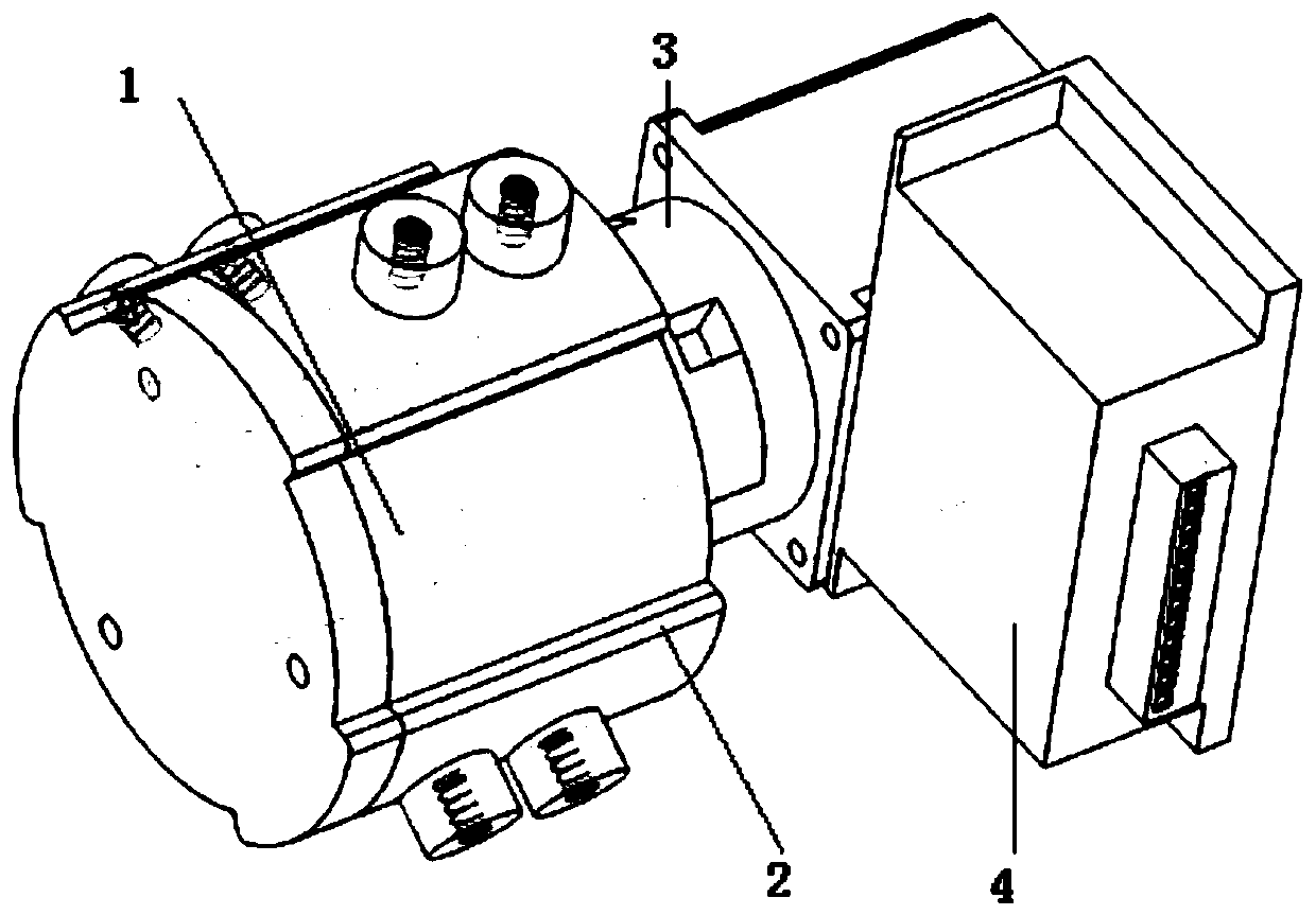
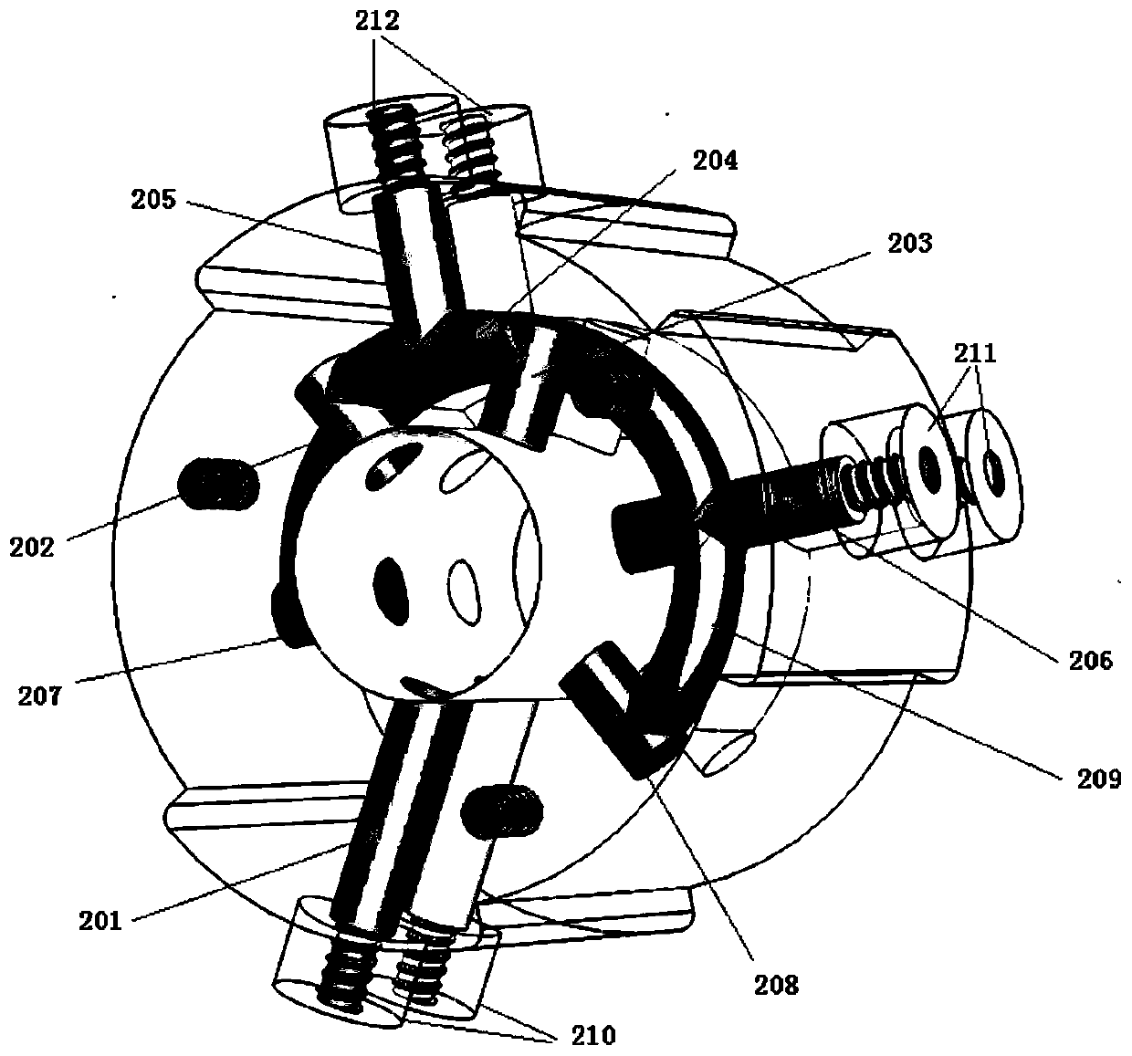
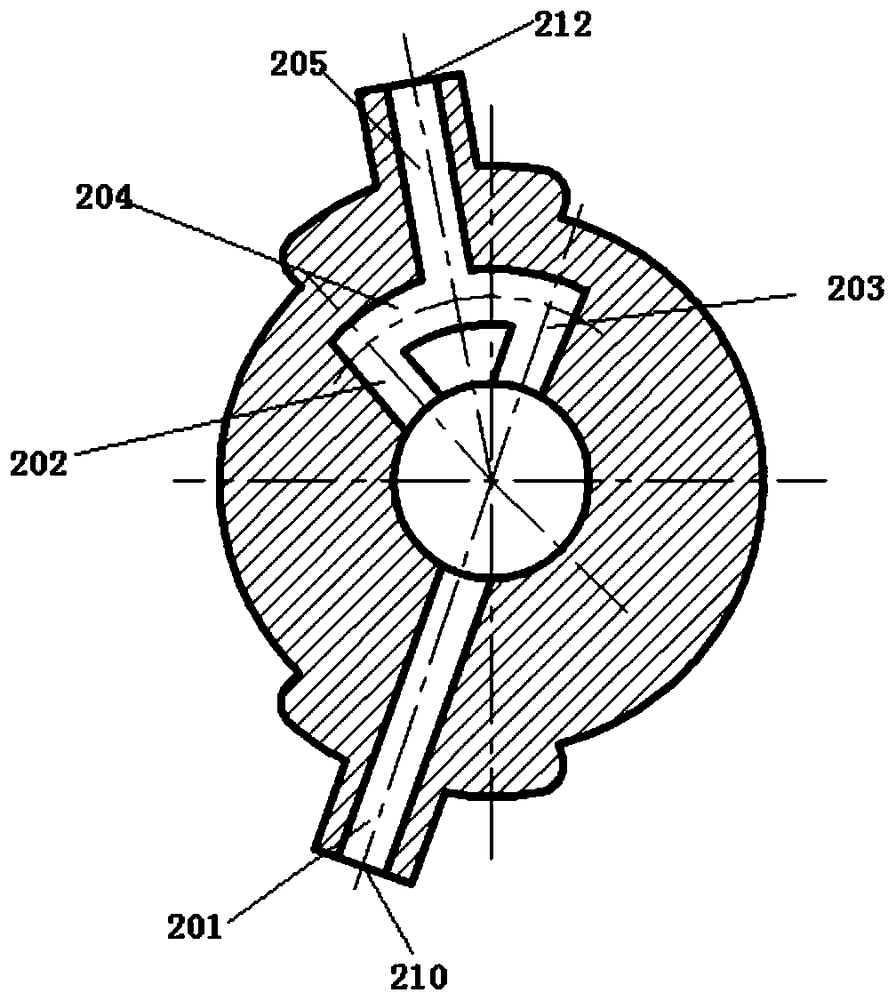
[0041] In this embodiment, the valve consists of 4 parts: valve core 1, valve seat 2, coupling 3, and power drive system. The structure is as follows: figure 1 . When it is applied, it will be fixed on the workbench of the pneumatic system. The structure is compact, safe and reliable. There are 8 effective reversing working status positions, as shown in Table 1. The through hole on the valve seat 2 cooperates, and the structure of the valve core 1 is as follows: image 3 As shown, the valve core 1 is a cylindrical shaft structure, and two planes are milled on the valve core 1 to form two cavities. Corresponding through-hole circuits are connected, so as to realize 8 reversing working states of different air supply, exhaust or cut-off. The rotation of the valve core 1 is realized by the power drive system 4, so the present invention can realize the pneumatic system according to the needs of users. The independent control of the air supply and exhaust process of the two chambe...


PUM


Abstract

The invention provides a multi-station pneumatic reversing valve. The multi-station pneumatic reversing valve comprises a valve seat, a valve core, a shaft coupling and a power driving system, whereinthe power driving system is used for driving the valve core to rotate in the inner cavity of the valve seat through the shaft coupling; the valve seat is provided with an air source supply hole, a cylinder air supply and exhaust hole and an external atmospheric air vent hole; the air source supply hole, the cylinder air supply and exhaust hole and the external atmospheric air vent hole are connected with a through loop inside the valve seat; and the valve core is matched with the through loop after rotation to realize switching of the given working state of the reversing valve. Through adoption of the multi-station pneumatic reversing valve, the technical problem of energy loss since exhausting needs to be performed at the other end when the pneumatic reversing valve switches to supply air to one side of the cylinder at a valve core station is solved.

Description

technical field [0001] The invention relates to a pneumatic transmission air supply and exhaust device, in particular to a multi-station pneumatic reversing valve which realizes supply and exhaust conversion through the rotation of a power drive system to drive a valve core to rotate. Background technique [0002] In the traditional pneumatic circuit, when the cylinder is extended or retracted, the intake port always inputs compressed gas during the entire stroke period of the piston, and the gas supply is not stopped until the piston reaches the end of the stroke. During this process, the piston The movement depends on the pressure of the compressed gas to do work, and the speed of the piston is controlled by the corresponding throttle valve. On the one hand, this control method will cause a large throttling pressure loss, and on the other hand, the expansion of the compressed gas can not be effective. Utilization means that when the piston needs to reversing movement, the ...

Claims


Application Information

Patent Timeline
IPC IPC(8): F16K11/085F16K27/06F16K5/04
CPCF16K11/085F16K27/065F16K5/0407
Inventor 熊伟姜忠爱王海涛度红望王志文刘神胡超春张啟晖林本末
Owner DALIAN MARITIME UNIVERSITY
Why Eureka
Try Eureka