
Testing device

A test device and device-under-test technology, which is applied in the direction of measuring device, measuring device casing, electronic circuit testing, etc., can solve the problem that single-chip packaging cannot meet the requirements of system design, etc., and achieve the effect of small size

Pending Publication Date: 2019-11-12
宁波吉品科技有限公司
View PDF0 Cites 12 Cited by
  • Summary
  • Abstract
  • Description
  • Claims
  • Application Information

AI Technical Summary

Problems solved by technology

In addition, due to the requirements of functional integration, single-chip packaging can no longer meet the requirements of system design, and packaging products are gradually developing from small-scale, single-chip packaging to large-scale, multi-chip packaging.

Method used


Image

  • Testing device
  • Testing device
  • Testing device

Examples


Embodiment Construction

[0030] The present invention will be further described in detail below in conjunction with the accompanying drawings and embodiments.

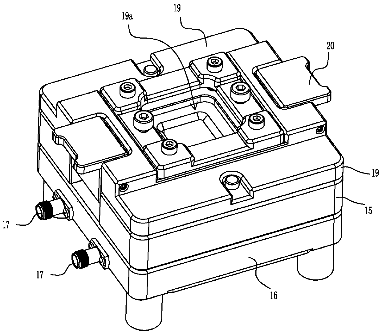
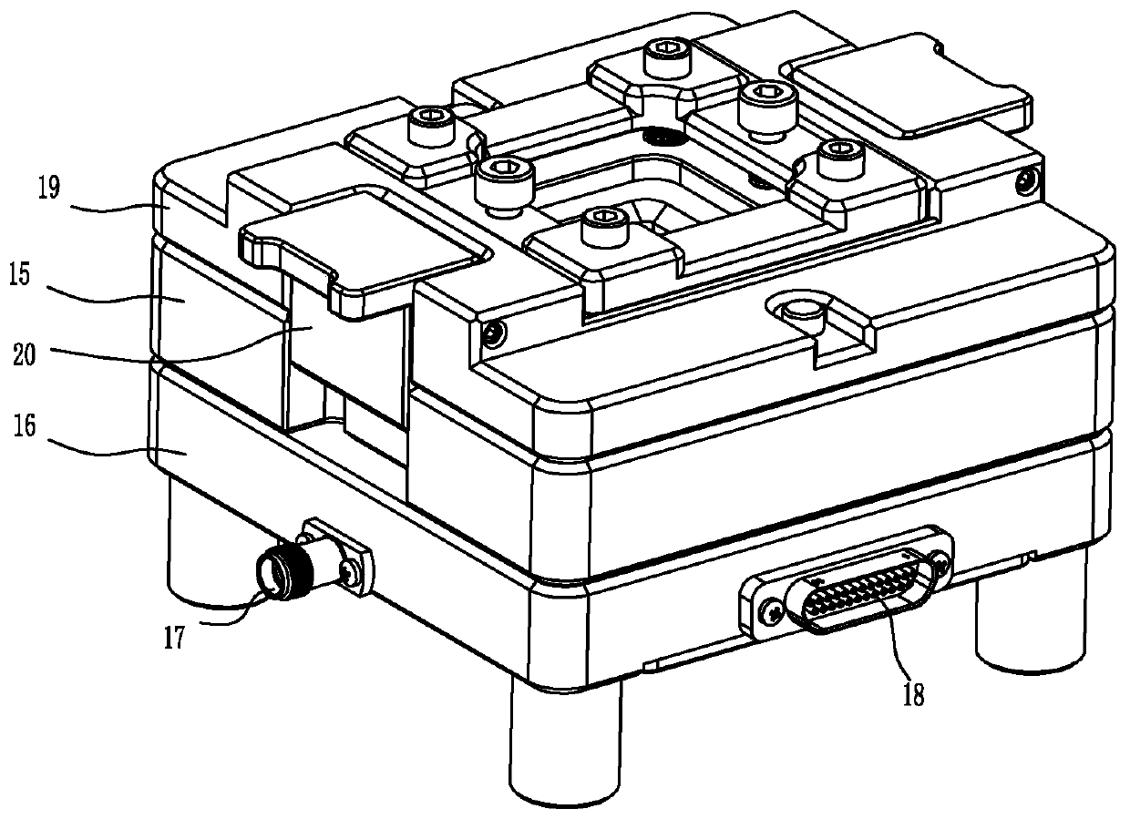
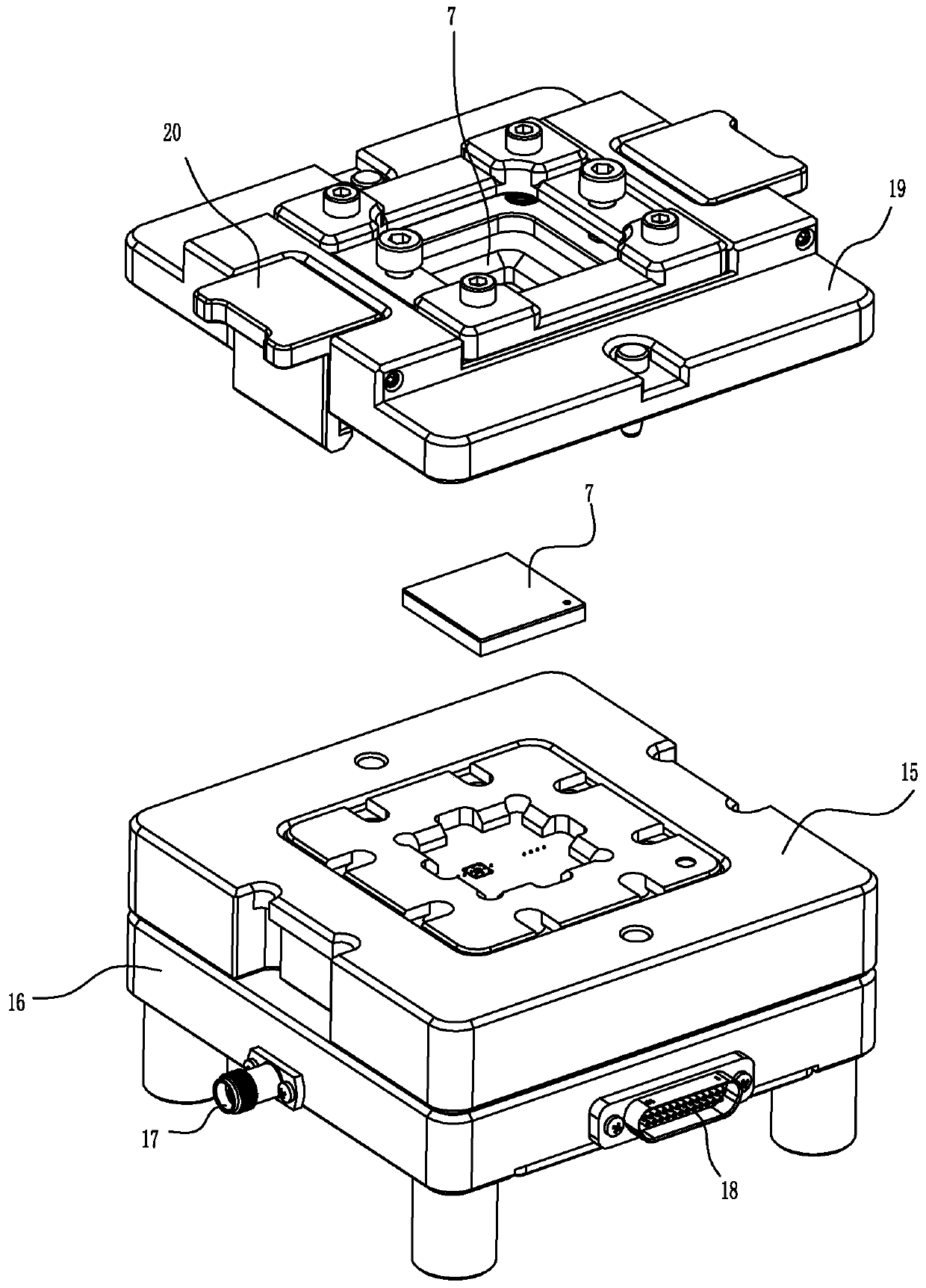
[0031] Such as Figure 1~4 The test device is used to test the device under test 7 containing the radio frequency signal terminal 71. It includes a main body 1, which is embedded with a radio frequency detection body 2 made of a conductor, and a radio frequency elastic body is provided in the radio frequency detection body. The probe 3, the outside of the radio frequency elastic probe is wrapped with an insulating sheath 4; the radio frequency detection body is also provided with a plurality of auxiliary elastic probes 5 surrounding the radio frequency elastic probe wrapped with the insulating sheath; the upper end of the radio frequency detection body is provided with The perforations that can be used for the radio frequency elastic probe and multiple auxiliary elastic probes respectively; The conductor 61 is conductively connected, and the ...


PUM


Abstract

The invention relates to a testing device, which is used for testing a tested device with a radio frequency signal terminal. The testing device is characterized by comprising a main body (1); a radiofrequency detection body (2) made of a conductor is embedded in the main body; a radio frequency elastic probe (3) is arranged in the radio frequency detection body; the radio frequency elastic probeis wrapped with an insulating sleeve (4); a plurality of auxiliary elastic probes (5) surrounding the radio frequency elastic probe wrapped with the insulation sleeve are further arranged in the radiofrequency detection body; the upper end of the radio frequency detection body (2) is provided with through holes for the radio frequency elastic probe (3) and the plurality of auxiliary elastic probes (5) to penetrate through; the upper end of the radio frequency elastic probe (3) can be in contact with the radio frequency signal terminal of the tested device; the lower end of the radio frequencyelastic probe is conductively connected with the conductor in a radio frequency cable; the auxiliary elastic probes are directly in conductive contact with the radio frequency detection body; and thelower end of the radio frequency detection body can be connected with the radio frequency cable.

Description

technical field [0001] The invention relates to a testing device, in particular to a tested device containing radio-frequency microwave signal terminals, such as testing BGA-packaged high-speed transmission chips and microsystem (SIP) products. Background technique [0002] Future information exchange is developing in the direction of wireless and mobile, and various wireless mobile technologies including mobile communication, wireless local area network, satellite communication, wireless access, radar detection, GPS positioning, etc. are developing vigorously. All of these systems require radio frequency (RF) technology, radio frequency integrated circuits (RFICs) or radio frequency systems. In these communication systems, people need to develop the signal spectrum extending to the radio frequency band or even the microwave and millimeter wave bands with higher frequencies. In addition, some ultra-high-speed integrated circuits also have the characteristics of radio frequen...

Claims


Application Information

Patent Timeline
Patent Type & Authority Applications(China)
IPC IPC(8): G01R31/00G01R31/28G01R1/04
CPCG01R31/00G01R31/2851G01R1/0408
Inventor 林斌詹昌吉
Owner 宁波吉品科技有限公司
Learn More