Lithium battery constant temperature device

A constant temperature device, lithium battery technology, applied in secondary batteries, battery pack components, circuits, etc., can solve problems such as reducing battery life, hidden dangers, and existing safety, so as to ensure charging and discharging performance, prolong service life, improve safety effect

Inactive Publication Date: 2019-11-12
TAIYUAN UNIVERSITY OF SCIENCE AND TECHNOLOGY
View PDF12 Cites 5 Cited by
  • Summary
  • Abstract
  • Description
  • Claims
  • Application Information

AI Technical Summary

Problems solved by technology

Since the working performance of the lithium battery is greatly affected by temperature, the lower the working temperature of the lithium battery, the more difficult the ion diffusion speed, which affects the charging and discharging performance of the battery, thus seriously affecting the service life of the lithium battery, and the higher the working temperature also affects the battery. Charge and discharge efficiency will eventually lead to degradation of battery material performance, reduce battery life and pose safety hazards; in order to ensure that the vehicle adapts to the external environment in different regions and keep the vehicle power system in the best state at all times, the lithium battery should always work at the optimal temperature Therefore, research on lithium battery constant temperature device and control system, so that the lithium battery pack is always in the optimal working temperature range during operation, which not only solves the problem of prolonging the service life of lithium batteries, but also improves the safety of lithium batteries.

Method used


Image

  • Lithium battery constant temperature device
  • Lithium battery constant temperature device
  • Lithium battery constant temperature device

Examples


Embodiment Construction

[0037] The following will clearly and completely describe the technical solutions in the embodiments of the present invention with reference to the accompanying drawings in the embodiments of the present invention. Obviously, the described embodiments are only some, not all, embodiments of the present invention. Based on the embodiments of the present invention, all other embodiments obtained by persons of ordinary skill in the art without making creative efforts belong to the protection scope of the present invention.

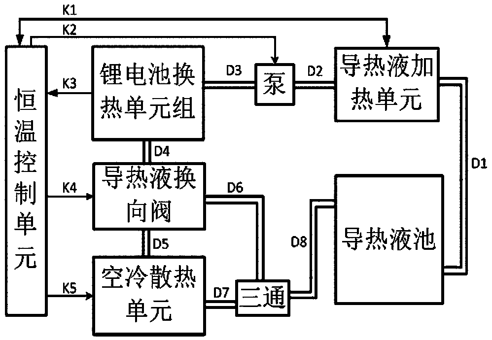
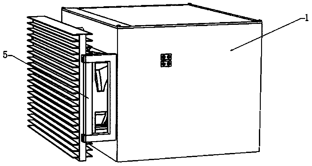
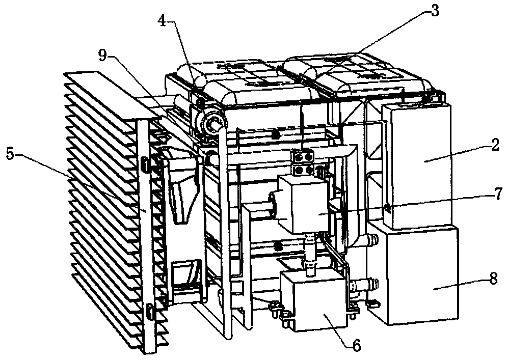
[0038] A lithium battery constant temperature device, such as figure 1 , figure 2 , image 3 As shown, it includes a constant temperature heat insulation box 1, the constant temperature heat insulation box 1 is a sandwich structure, and heat insulation material is added between the two metal layers. The constant temperature heat insulation box 1 includes a heat exchange part and a control part, the heat exchange part includes a lithium battery heat exchange...


PUM


Abstract

The invention belongs to the field of constant temperature devices, and particularly relates to a lithium battery constant temperature device. The lithium battery constant temperature device comprisesa constant temperature heat insulation box; the constant temperature heat insulation box has a sandwich structure and comprises a heat exchange part and a control part; the constant temperature heatinsulation box is connected with an air-cooled heat dissipation unit; the constant temperature control unit is also connected with a lithium battery heat exchange unit, a heat conducting fluid reversing valve, the air-cooled heat dissipation unit, a pump and a heat conducting fluid heating unit; the lithium battery heat exchange unit is connected with the heat conducting fluid heating unit throughthe pump; the heat conducting fluid reversing valve is connected with the lithium battery heat exchange unit and the air-cooled heat dissipation unit; the heat conducting fluid heating unit is connected with a heat conducting fluid pool; and the heat conducting fluid pool is connected with the heat conducting fluid reversing valve and the air-cooled heat dissipation unit through a tee joint. Thelithium battery pack can be made to constantly work in the best temperature range, the service life of the battery is prolonged, and the safety is improved. The lithium battery constant temperature device is used for constant temperature control on an electric vehicle lithium battery.

Description

technical field [0001] The invention belongs to the field of constant temperature devices, in particular to a lithium battery constant temperature device. Background technique [0002] As the problems of environmental pollution and resource scarcity become more and more prominent, the development of new energy vehicles, especially electric vehicles, has become the general trend. As an energy supply device for electric vehicles, automotive lithium batteries have directly become an important part of restricting its development. Since the working performance of the lithium battery is greatly affected by temperature, the lower the working temperature of the lithium battery, the more difficult the ion diffusion speed, which affects the charging and discharging performance of the battery, thus seriously affecting the service life of the lithium battery, and the higher the working temperature also affects the battery. Charge and discharge efficiency will eventually lead to degrada...

Claims


Application Information

Patent Timeline
Patent Type & Authority Applications(China)
IPC IPC(8): H01M10/613H01M10/615H01M10/617H01M10/625H01M10/633H01M10/637H01M10/6554H01M10/6556H01M10/6563H01M10/6568H01M10/6571H01M10/658H01M10/48H01M2/10
CPCH01M10/613H01M10/615H01M10/617H01M10/625H01M10/633H01M10/637H01M10/658H01M10/6556H01M10/6563H01M10/6568H01M10/6554H01M10/6571H01M10/488H01M10/486H01M50/20Y02E60/10
Inventor 朱艳春李子良马立峰申宇杰邹景锋
Owner TAIYUAN UNIVERSITY OF SCIENCE AND TECHNOLOGY
Why Eureka
Try Eureka