Eureka AIR delivers breakthrough ideas for toughest innovation challenges, trusted by R&D personnel around the world.

Method for machining outer circumferential surface groove of thin-wall disc-shaped workpiece

A processing method and technology of thin-walled discs, which are applied in metal processing equipment, manufacturing tools, accessories of tool holders, etc., can solve problems such as long processing time, tool wear, and difficult to guarantee dimensional accuracy, so as to improve processing accuracy and processing quality , Reduce processing costs, reduce the effect of workpiece deformation

Inactive Publication Date: 2019-11-15
GUIZHOU LIYANG INT MFG
View PDF0 Cites 0 Cited by
  • Summary
  • Abstract
  • Description
  • Claims
  • Application Information

AI Technical Summary

Problems solved by technology

In the existing processing technology, first, the processing method of turning first and then milling is usually used. Due to the poor rigidity of thin-walled parts, after the milling process is completed, the parts will deform greatly, resulting in out-of-tolerance thickness dimensions, which are difficult to meet the design requirements; It adopts the processing method of milling first and then turning. In the processing process of this method, due to the poor rigidity of the parts, the amount of tool clearance of each boss is different when entering the tool or cutting and when withdrawing the tool. As a result, each boss after processing is completed. There is a certain slope, and the dimensional accuracy is difficult to guarantee; in addition, this machining process is discontinuous cutting, the tool wears seriously, affects the life of the tool, and is prone to knife punching; and this processing method requires repeated cutting, long processing time, and tool consumption High, not conducive to mass production

Method used


Image

  • Method for machining outer circumferential surface groove of thin-wall disc-shaped workpiece
  • Method for machining outer circumferential surface groove of thin-wall disc-shaped workpiece

Examples


Embodiment Construction

[0021] The technical solution of the present invention is further described below, but the scope of protection is not limited to the description.

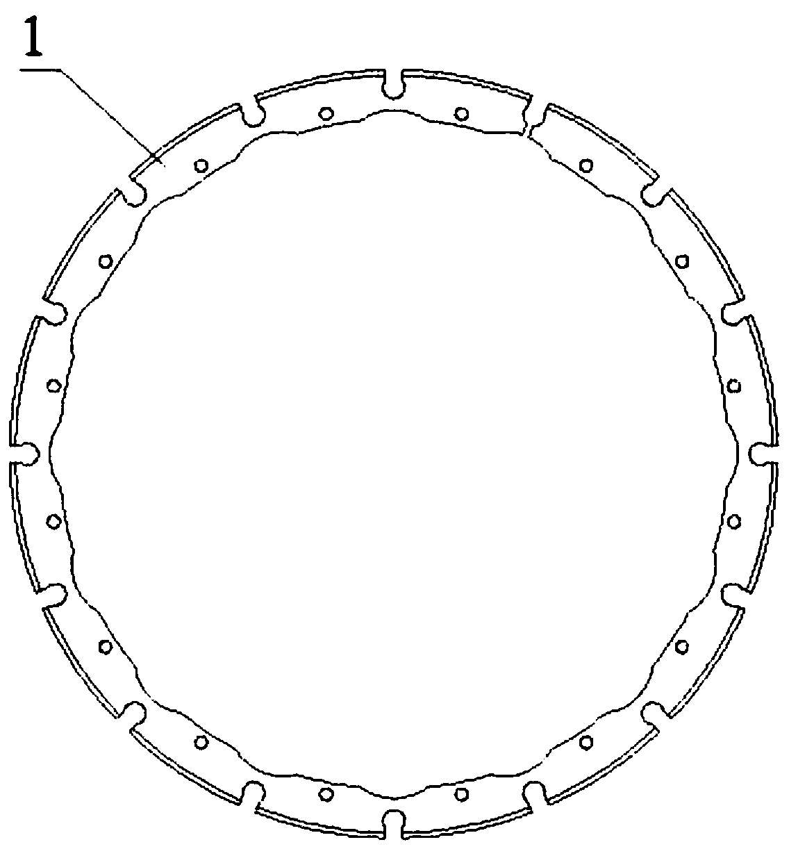
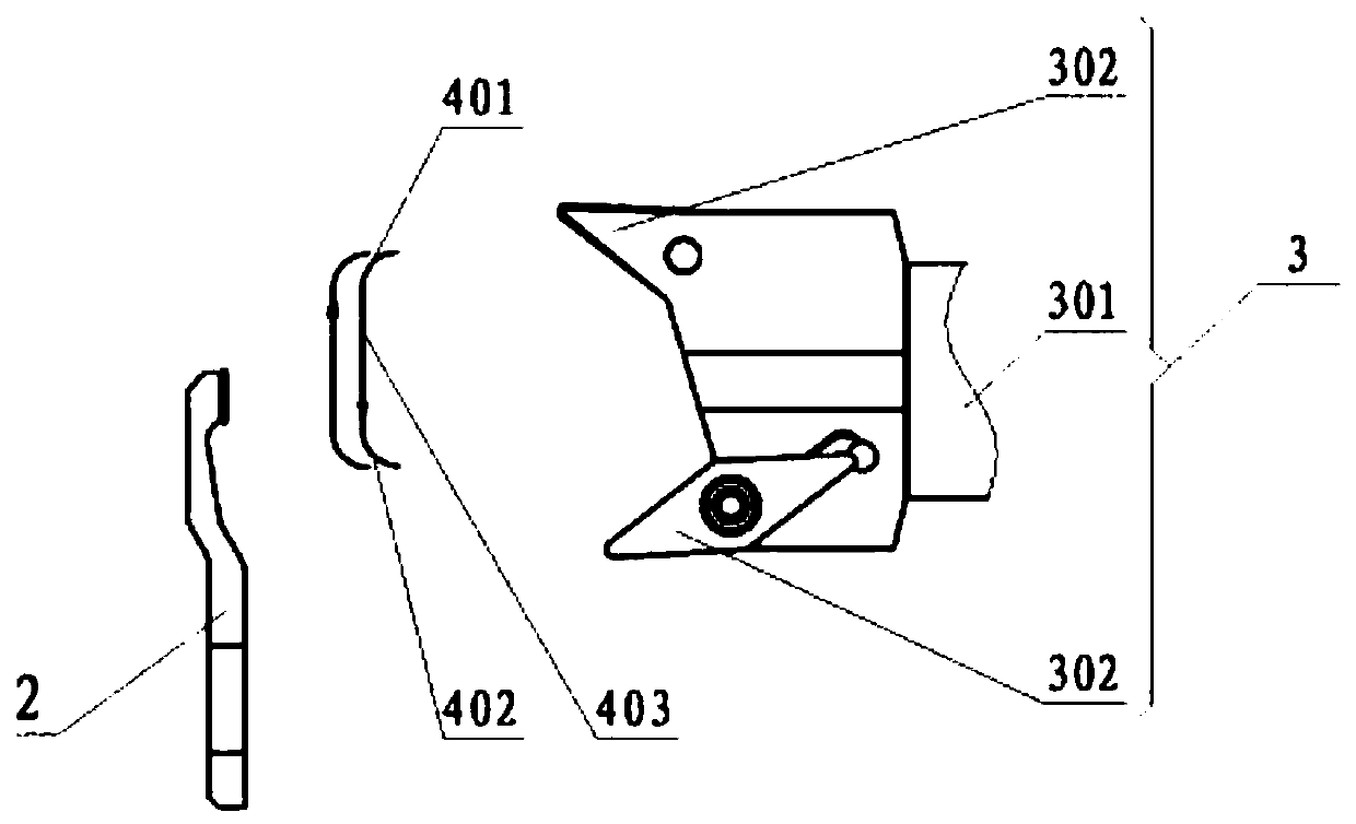
[0022] Such as figure 1 , figure 2 As shown, the present invention provides a kind of processing method of the groove of outer peripheral surface of thin-walled disc-shaped part, comprises the following steps:

[0023] Prepare the thin-walled disc-shaped workpiece 2 and the tool 3, clamp the thin-walled disc-shaped workpiece 2 on the lathe spindle, clamp the tool 3 on the tool holder of the lathe, drive the thin-walled disc-shaped workpiece 2 to rotate through the lathe spindle, and move During the process that the tool 3 removes material on the outer peripheral surface of the thin-walled disc-shaped workpiece 2 to obtain groove features, the rotation direction of the thin-walled disc-shaped workpiece 2 is reversely changed at least once. Further, a wear-resistant layer can also be coated on the surface of the cutter 3 to increa...


PUM


Abstract

The invention provides a method for machining an outer circumferential surface groove of a thin-wall disc-shaped workpiece. The method comprises the following steps of preparing a thin-walled disc-shaped workpiece and a cutter, clamping the thin-walled disc-shaped workpiece on a lathe main shaft, clamping the cutter on a lathe cutter rest, driving the thin-walled disc-shaped workpiece to rotate through a lathe spindle, and reversely converting the thin-walled disc-shaped workpiece in the rotating direction at least once in the process of cutting off the outer circumferential surface of the thin-walled disc-shaped workpiece to obtain the groove features. According to the technical scheme, the direction of the cutting force acting on the thin-walled disc-shaped workpiece is alternately changed in the machining process by changing the rotating direction of the lathe spindle, the deformation of the workpiece generated by the cutting force action is counteracted at a certain degree, the workpiece deformation is reduced, and the machining precision and machining quality of the thin-walled disc-shaped workpiece are improved; and in addition, according to the method, the v-shaped cutter ispreferably adopted for machining, so that the cutter abrasion is reduced, the service life of the cutter is prolonged, and the processing cost is reduced.

Description

technical field [0001] The invention belongs to the technical field of mechanical processing, and in particular relates to a processing method for a groove on the outer peripheral surface of a thin-walled disc-shaped part. Background technique [0002] In the field of manufacturing, in the machining industry, thin-walled parts are a common feature, and the processing of thin-walled parts is a difficult problem in China, because thin-walled parts have poor rigidity, weak strength, and are easy to deform during processing. For example, on the parts of a certain type of aero-engine, there is a thin-walled disc-shaped annular part with a wall thickness of up to 1.9 mm and a minimum of 1 mm, with 16 grooves on the outer circle, and an annular boss on the upper end of the outer circle. , is cut into 16 pieces by 16 grooves, the 16 bosses have a height dimension with the reference plane, and the size requirements are high. In the existing processing technology, first, the processi...

Claims


Application Information

Patent Timeline
Patent Type & Authority Applications(China)
IPC IPC(8): B23B5/00B23B27/10B23B5/48
CPCB23B5/00B23B5/48B23B27/10
Inventor 杨志伟严萍何明航王正北李井平
Owner GUIZHOU LIYANG INT MFG
Why Eureka
Eureka Blog
Learn More