
Polishing rod used for machining slotted hole and polishing method

A polishing rod and waist-shaped hole technology, applied in metal processing equipment, grinding/polishing equipment, manufacturing tools, etc., can solve the problems of leaving very obvious grinding marks, complicated production procedures, and uncontrollable polishing effects. Achieve the effects of reducing capital investment and space occupation, excellent mirror effect, and reducing dust pollution

Pending Publication Date: 2019-11-15
LENS TECH
View PDF0 Cites 4 Cited by
  • Summary
  • Abstract
  • Description
  • Claims
  • Application Information

AI Technical Summary

Problems solved by technology

The product processed by this method has poor polishing effect, high roughness, and poor mirror effect; in addition, because the chamfering position of the waist-shaped hole is an inclined-plane structure, it is easy to form a polishing dead angle for grinding skin and then cause the polishing effect to be uncontrollable, and the CPK value ( That is, the process capability index refers to the actual processing capacity of the process in a stable state for a certain period of time) is low. In order to ensure product quality, it is often necessary to process the chamfering position of the needle waist hole separately or rework unqualified products , which complicates the production process
[0004] Some factories improve the traditional polishing method by using brushes instead of microdermabrasion for polishing operations. Although the existence of polishing dead angles is reduced to a certain extent and the polishing effect is more uniform, the damage of the brush itself to the hole wall is very large. Large, it will leave very obvious wear marks during the polishing process, which is of no help to improve the roughness of the hole wall and the mirror effect, and may even have a negative effect

Method used


Image

  • Polishing rod used for machining slotted hole and polishing method
  • Polishing rod used for machining slotted hole and polishing method
  • Polishing rod used for machining slotted hole and polishing method

Examples


Embodiment 1

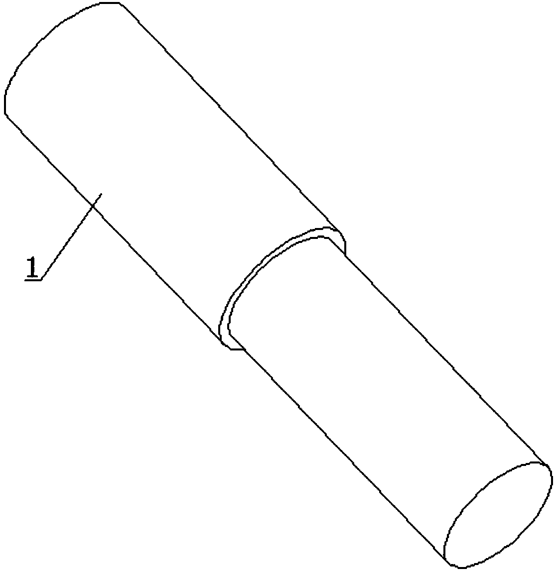
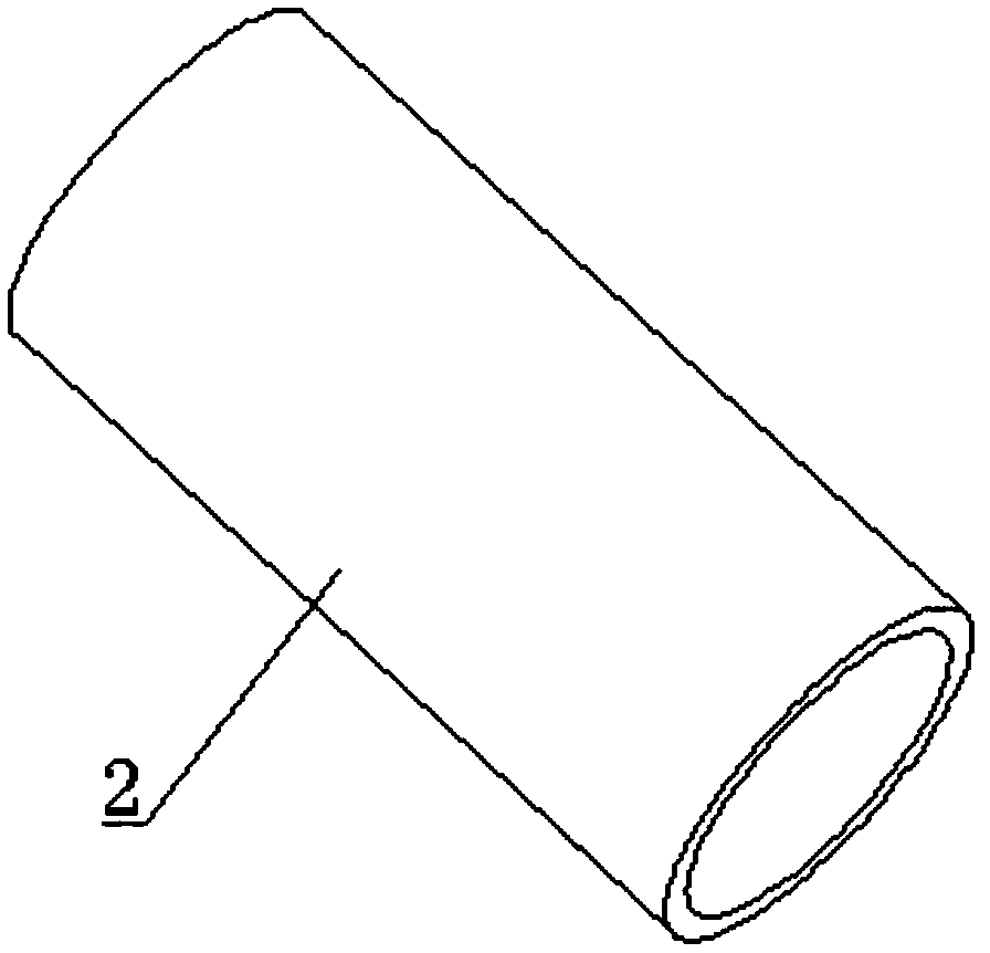
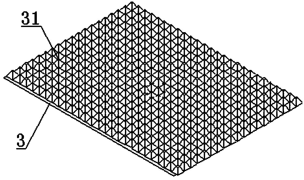
[0037] see Figure 1-Figure 6 , a polishing rod for processing waist-shaped holes, comprising a metal rod body 1 whose upper end is fixedly connected to a CNC machining shaft, a latex tube sleeve 2 sleeved at the lower end of the metal rod body 1, and wrapped in the latex tube Set of 2 exterior buffing microdermabrasion3.

[0038] A plurality of tiny cones 31 are arranged on the outer surface of the polishing skin 3 , and the cones 31 have a quadrangular pyramid structure and are arranged in a linear array. In this embodiment, the bottom of the cone 31 is a square of 2mm×2mm and its height is 1.5mm. The angle between two adjacent edges at the top of the cone 31 is 25°. The distance between the sides of the bottom of the cone is 2.1mm.

[0039] In this embodiment, the axial length of the polishing buffing skin 3 is 10 times the depth of the waist hole 01, correspondingly, the buffing buffing skin 3 is divided into 10 annular processing areas in the direction of its axial leng...


PUM


Abstract

The invention provides a polishing rod used for machining a slotted hole and a polishing method. The polishing rod comprises a metal rod body, a latex tube sleeve and a polishing grinding surface, wherein the upper end of the metal rod body is fixedly connected with a CNC machining shaft, the latex tube sleeve is arranged at the lower end of the metal rod body in a sleeving mode, the polishing grinding surface is wrapped around the exterior of the latex tube sleeve, a plurality of tiny conical bodies are arranged on the outer surface of the polishing grinding surface, and the polishing grinding surface is divided into 5-15 annular machining areas in the axial length direction thereof. When the polishing rod is adopted for polishing operation, the polishing rod is firstly moved into the slotted hole, in addition, the polishing grinding surface is made to make contact with the hole wall of the slotted hole, then the polishing rod is driven to spin and move circularly in the circumferential direction in the slotted hole, meanwhile, a cooling liquid is continuously sprayed to achieve the purposes of cooling and polishing assisting, and when one machining area of the polishing grindingsurface is worn out and fails, the polishing rod is moved so that switching to another machining area can be realized and operation continues. According to the polishing rod, the production efficiencycan be effectively improved, the polishing effect on the beveled slotted hole is good, and the product roughness requirement is met.

Description

technical field [0001] The invention relates to the technical field of hole wall processing, in particular to a polishing rod and a polishing method for processing waist-shaped holes. Background technique [0002] At present, in the mobile phone and other electronic product industries, glass backplanes and touch screens are increasingly used in related applications, and the structures of openings on them (such as cameras, HOME buttons, etc.) are also becoming more and more complicated. There is a kind of chamfered waist-shaped hole used on the glass mobile phone panel. On the basis of the structure of the ordinary waist-shaped hole, an outward-sloping horn-shaped opening is added to facilitate the positioning and assembly of other components during installation. At the same time Avoid corner damage; but this structure also increases the processing difficulty of the inner wall of the waist hole accordingly, resulting in unstable product quality. [0003] The traditional poli...

Claims


Application Information

Patent Timeline
Patent Type & Authority Applications(China)
IPC IPC(8): B24D7/18B24D18/00
CPCB24D7/18B24D18/00
Inventor 周群飞曾涛
Owner LENS TECH
Learn More