Steel strip ion coating coloring process

An ion coating and steel strip technology, applied in ion implantation coating, metal material coating process, sputtering coating, etc., can solve the problems of high target consumption, limited sputtering distance, low film brightness, etc. The film has high density, stable titanium coating, and uniform and stable color plating.

Inactive Publication Date: 2019-11-15
ZHAOQING HONGWANG METAL IND
View PDF5 Cites 4 Cited by
  • Summary
  • Abstract
  • Description
  • Claims
  • Application Information

AI Technical Summary

Problems solved by technology

[0003] The first type: uniform rows of massive targets are distributed in all directions of the furnace wall. There are a large number of them. The targets are funnel-shaped to sputter towards the rotating steel plate in the middle. If the sputtering is too scattered, it will damage the entire furnace body. The internal objects are all sputtered, and the target consumption is relatively large; although the sputtering rate is fast, it will cause uneven color difference on the plate surface, and the distance of sputtering is limited, and the distance between the target and the steel plate is limited. If the distance is too far, the sputtering effect will not be good, and the brightness of the film will be low; if the distance is too close, the phenomenon of coloring of the steel plate will occur due to excessive sputtering, and even the steel plate will be burned due to excessive temperature.
[0004] The second type: columnar target. There are two modes of columnar target. One is that the target is located in the middle, and the steel plate rotates around the target. However, the installation of the target in this mode requires driving, which is not easy to install and has potential safety hazards.
Another mode is that multiple cylindrical targets are distributed along the furnace wall, and the steel strip is rotated in the middle for coating, which requires more targets, resulting in waste of targets

Method used


Image

  • Steel strip ion coating coloring process

Examples


Embodiment Construction

[0023] Specific embodiments of the present invention will be described in detail below in conjunction with the accompanying drawings. It should be understood that the specific embodiments described here are only used to illustrate and explain the present invention, and are not intended to limit the present invention.

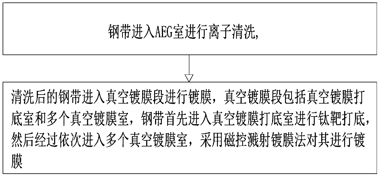
[0024] Such as figure 1 Shown, steel strip ion coating coloring process of the present invention comprises the following steps:

[0025] S1: The steel strip enters the AEG chamber (ie: vacuum cleaning chamber) for ion cleaning. The AEG chamber is equipped with an anode rod and a cleaning target, and the anode rod is located above the cleaning target; Argon is introduced into the AEG chamber in a high vacuum environment Gas, through the glow discharge of argon gas, high-energy argon ions are generated, and the high-energy argon ions bombard the steel strip at high speed under the action of the magnetic field and the anode rod, and the attachments adhering to the...


PUM


Abstract

The invention provides a steel strip ion coating coloring process. The process comprises the following steps that S1, a steel strip enters an AEG chamber for ion cleaning, an anode rod and a cleaningtarget material are mounted in the AEG chamber, and the anode rod is located above the cleaning target material; and argon is introduced into the AEG chamber in a high vacuum environment, high-energyargon ions are generated through glow discharge of the argon, and bombards the steel strip at a high speed under the action of a magnetic field and an anode bar. The cleaned steel strip enters a vacuum coating section for coating, and the vacuum coating section comprises a vacuum coating bottoming chamber and a plurality of vacuum coating chambers; and the steel strip enters a vacuum coating bottoming chamber to be subjected to target bottoming, and then enters the plurality of vacuum coating chambers in sequence, and is subjected to coating through a magnetron sputtering coating method. The steel strip ion coating coloring process has the advantages that the sputtering speed is high, the coating effect is good after sputtering, the color is uniform, the color difference is small, and theconsumption of the target material is small.

Description

technical field [0001] The invention relates to the technical field of steel strip production, in particular to a steel strip ion coating coloring process. Background technique [0002] The existing steel strip coating ion coloring process has the following two types: [0003] The first type: uniform rows of massive targets are distributed in all directions of the furnace wall. There are a large number of them. The targets are funnel-shaped to sputter towards the rotating steel plate in the middle. If the sputtering is too scattered, it will damage the entire furnace body. The internal objects are all sputtered, and the target consumption is relatively large; although the sputtering rate is fast, it will cause uneven color difference on the plate surface, and the distance of sputtering is limited, and the distance between the target and the steel plate is limited. If the distance is too far, the sputtering effect will not be good, and the brightness of the film will be low;...

Claims


Application Information

Patent Timeline
Patent Type & Authority Applications(China)
IPC IPC(8): C23C14/56C23C14/02C23C14/16C23C14/35
CPCC23C14/022C23C14/025C23C14/165C23C14/35C23C14/562C23C14/568
Inventor 刘自然卢威陈元钟日新何振缪朴
Owner ZHAOQING HONGWANG METAL IND
Why Eureka
Try Eureka