UAV selective obstacle avoidance system and method based on binocular vision and three-axis pan/tilt

A binocular vision, machine-selective technology, applied in control/regulation systems, three-dimensional position/channel control, non-electric variable control, etc., can solve the problem that ultrasonic waves cannot accurately locate obstacles, have a large impact, and require a large amount of calculation. problem, to achieve the effect that is conducive to autonomous obstacle avoidance

Inactive Publication Date: 2019-11-15
TAIZHOU UNIV
View PDF0 Cites 10 Cited by
  • Summary
  • Abstract
  • Description
  • Claims
  • Application Information

AI Technical Summary

Problems solved by technology

Infrared is sensitive to external conditions such as light; at present, radar ranging technology is not mature, and there is a problem of misjudgment; ultrasonic waves cannot accurately locate obstacles, and the ranging range is limited; when binocular ranging or identifying obstacles, binocular cameras The angle of view is limited and the amount of calculation is large, and the external light has a great influence on it, so it is difficult to achieve 360° no dead angle obstacle avoidance
[0003] When the multi-rotor UAV is flying forward, the UAV is in a tilted state, and the distance measured by the binocular vision may not be the horizontal actual distance between the UAV and the ground or obstacles, and unnecessary avoidance will occur. Obstacles or hovering, so that the UAV cannot avoid obstacles according to our expected rules, which will greatly increase the possibility of UAV collisions, thereby reducing the practicability and reliability of the binocular obstacle avoidance system

Method used


Image

  • UAV selective obstacle avoidance system and method based on binocular vision and three-axis pan/tilt
  • UAV selective obstacle avoidance system and method based on binocular vision and three-axis pan/tilt
  • UAV selective obstacle avoidance system and method based on binocular vision and three-axis pan/tilt

Examples


Embodiment Construction

[0076] In order to make the purpose, technical solution and advantages of the present invention clearer, the following in conjunction with the attached Figure 1-8 , to further describe the present invention in detail.

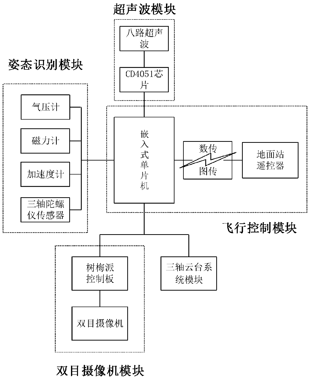
[0077] refer to figure 1 , UAV selective obstacle avoidance system and control method based on binocular vision and three-axis gimbal, characterized in that the obstacle avoidance system includes a multi-channel ultrasonic module, a raspberry pie control board, a binocular ranging module, Three-axis gimbal system module, UAV attitude recognition module, flight control module and transmission module.

[0078] The multi-channel ultrasonic module includes eight ultrasonic waves and a CD4051 chip around the drone, which are used to detect whether there are obstacles in the surrounding environment, measure the distance to obstacles, simply judge whether to avoid obstacles and use binocular cameras; ultrasonic measurement Range: horizontal viewing angle 60°, verti...


PUM


Abstract

The invention discloses a UAV selective obstacle avoidance system and method based on binocular vision and three-axis pan/tilt, and the method comprises the following steps of opening eight-way ultrasonic and binocular vision, and determining a flight direction angle of the UAV; rotating the binocular camera to the flight direction by the three-axis pan/tilt for opening, and monitoring the flightdirection environment in real time; acquiring depth information; comprehensively analyzing the orientation of the obstacle and the distance between the obstacle and the UAV based on the obstacle imagecaptured by the binocular camera and the pitch angle and roll angle acquired by the UAV gesture recognition module; judging whether to avoid the obstacle by a tree plum control panel; opening a selective obstacle avoidance mode; and planning the surrounding environment of the UAV and the eight-way ultrasonic obstacle avoidance. The method provided by the invention not only greatly reduces the cost, but also observes the surrounding environment at 360 degrees without dead angles and reduces the load when the UAV is autonomously flying. The use of the three-axis pan/tilt removes the offset of the pitch and roll angle of the UAV on the pixel flight frame during flight and ensures flight safety.

Description

technical field [0001] The invention relates to the field of UAV obstacle avoidance technology, in particular to a UAV selective obstacle avoidance system and method based on binocular vision and three-axis pan-tilt. Background technique [0002] With the development of the UAV market, the requirements for automatic perception and control of UAVs are getting higher and higher, especially in terms of obstacle avoidance, so that UAVs can complete flight tasks in complex environments. Commonly used obstacle avoidance devices include infrared, radar, ultrasonic and binocular ranging modules. Infrared is sensitive to external conditions such as light; at present, radar ranging technology is not mature, and there is a problem of misjudgment; ultrasonic waves cannot accurately locate obstacles, and the ranging range is limited; when binocular ranging or identifying obstacles, binocular cameras The angle of view is limited and the amount of calculation is large, and the external li...

Claims


Application Information

Patent Timeline
Patent Type & Authority Applications(China)
IPC IPC(8): G05D1/08G05D1/10
CPCG05D1/0808G05D1/101
Inventor 邬玲伟许建华王嘉琨梅盼楼梦瑶
Owner TAIZHOU UNIV
Why Eureka
Try Eureka