Device for coupling large-divergence angle laser into single-mode fiber and method

A single-mode fiber, large divergence technology, applied in the field of fiber, can solve the problems of equipment waste, inability to use laser, and extremely high processing requirements.

Inactive Publication Date: 2019-11-19
珠海达明科技有限公司
View PDF1 Cites 3 Cited by
  • Summary
  • Abstract
  • Description
  • Claims
  • Application Information

AI Technical Summary

Problems solved by technology

However, this solution has extremely high requirements for the processing of the instrument. The focal length of the collimator alone reaches 5m, resulting in the size of the overall device being more than 5m. The equipment for auxiliary alignment must be left in the coupling optical path after use, resulting in Waste of equipment, etc.
Therefore, it is difficult to apply to the industrial field
And it is only suitable for coupling the quasi-parallel light emitted from the laser, and cannot be applied to the laser with a large divergence angle emitted from the semiconductor chip

Method used


Image

  • Device for coupling large-divergence angle laser into single-mode fiber and method
  • Device for coupling large-divergence angle laser into single-mode fiber and method
  • Device for coupling large-divergence angle laser into single-mode fiber and method

Examples


Embodiment Construction

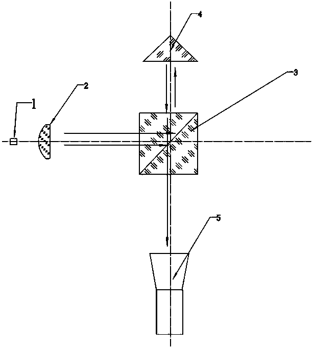
[0032] Such as Figure 1 to Figure 5 Shown, the present invention will be described in more detail below in conjunction with accompanying drawing.

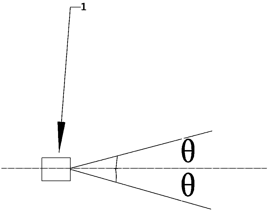
[0033] Such as figure 1 A laser 1 to be coupled into an optical fiber is shown, the divergence angle of the laser is 2θ, and the dotted line in the figure indicates the optical axis.

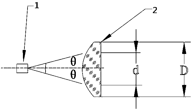
[0034] Such as figure 2 As shown, the light-emitting surface of the laser 1 is placed on the object focus of the collimating mirror 2, and the focal length of the collimating mirror 2 is set to f 1 , the wave aberration RMS value should be less than 1 / 10λ, where λ is the wavelength of the incident light. In this embodiment, an aspheric lens is used. D needs to meet:. After being collimated by the collimating mirror, the laser light becomes parallel light parallel to the optical axis, and the diameter of the spot is d. In this embodiment, the collimating lens is an aspheric lens with a focal length of 10 mm. If the luminous center of the laser...


PUM


Abstract

The invention provides a device for coupling large-divergence angle laser into a single-mode fiber and a method. The device is simple in structure, small in size and can assist in saving resources. Light emitted by a laser is collimated by a collimating mirror; the collimated light is split into transmitted light and reflected light after passing through a beam splitter prism. The reflected lightenters a pyramid prism; and after the reflected light is reflected along an original path, the reflected light is absorbed by an industrial camera and forms a reference light spot. The transmitted light split by the beam splitter enters a microscopic objective lens; after being converged, the transmitted light enters an optical fiber; the coupling end surface of the optical fiber reflects a part of the incident light, and the partially reflected light is returned to the beam splitter prism along an original path; the returned reflected light is reflected by the reflecting surface of the beam splitter prism, and then, the reflected light is absorbed by the industrial camera and then forms a coupled light spot; and if the coupled light spot is completely overlapped with the reference light spot, the light emitted by the laser is coupled into the optical fiber, and otherwise, the pose of the optical fiber is adjusted until the coupled light spot is completely overlapped with the referencelight spot. The device and method can be applied to the field of optical fibers.

Description

technical field [0001] The invention relates to the field of optical fibers, in particular to a device and method for coupling single-mode optical fibers with large divergence angle lasers. Background technique [0002] Fiber optic cable communication is the main transmission mode of modern communication transmission system. The development history of fiber optic cable is only 10 to 20 years, and it has experienced three upgrades: short wavelength multimode fiber optic cable, long wavelength multimode fiber optic cable and long wavelength single mode fiber optic cable . As a brand-new information transmission technology, optical fiber communication technology has become the main communication mode of modern communication, almost replacing traditional copper cable communication technology, and plays a very important role in modern information network. It has been widely used in many fields and industries The application has become an important means to improve the quality an...

Claims


Application Information

Patent Timeline
IPC IPC(8): G02B6/42
CPCG02B6/4204G02B6/4222G02B6/4296
Inventor 王灵光赖宣润黄丽芳王成坤
Owner 珠海达明科技有限公司
Why Eureka
Try Eureka