Eureka AIR delivers breakthrough ideas for toughest innovation challenges, trusted by R&D personnel around the world.

Mold storage limiter

A stopper and mold technology, applied in the field of stamping molds, can solve the problems of large mold volume, loss of kinetic energy of machine tool tonnage, and increased cost of nitrogen cylinder storage, and achieve the goal of reducing manual operation, reducing kinetic energy loss, and reducing force source Effect

Active Publication Date: 2019-11-22
CHERY AUTOMOBILE CO LTD
View PDF6 Cites 0 Cited by
  • Summary
  • Abstract
  • Description
  • Claims
  • Application Information

AI Technical Summary

Problems solved by technology

However, due to the large size of the mold, and in order to save storage space, the mold warehouses of many companies stack three layers of molds. The nitrogen cylinder limiter of the bottom set of molds needs to support the weight of the upper mold of this set of molds and the weight of the other two sets of molds. Weight, the nitrogen cylinder needs to provide a very large force, and the cost of the nitrogen cylinder is proportional to the force provided, which greatly increases the cost of the nitrogen cylinder storage
At the same time, in the production process, since the nitrogen cylinder does not need to be removed, the press must balance the force of the nitrogen cylinder limiter, resulting in the consumption of machine tool tonnage and loss of kinetic energy

Method used


Image

  • Mold storage limiter
  • Mold storage limiter
  • Mold storage limiter

Examples


Embodiment Construction

[0030] Below in conjunction with accompanying drawing, the present invention will be further described:

[0031] Figure 1 to Figure 8 A specific implementation manner of a mold storage limiter of the present invention is shown.

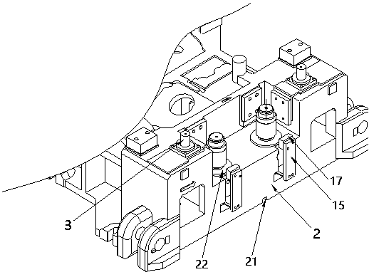
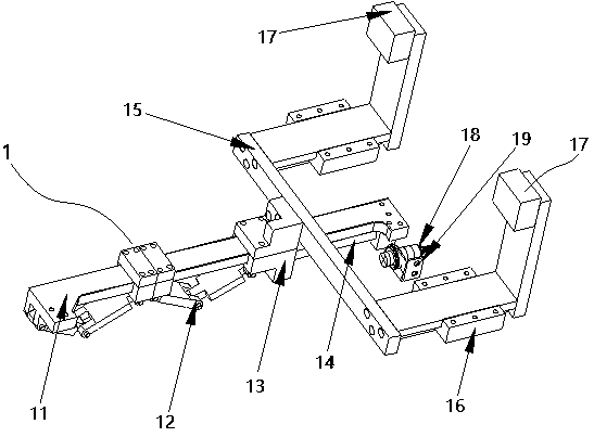
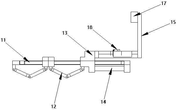
[0032] Such as Figure 1 to Figure 8 As shown, the mold storage limiter in this embodiment includes a rigid limiter 1 and an elastic limiter 3 arranged on the lower mold base 2, and the rigid limiter 1 and the elastic limiter 3 are used in combination; the rigid limiter The positioner 1 comprises a guide rod 11, a slide block 13 and a limit block 17, the two ends of the guide rod 11 are installed on the lower mold base 2, the slide block 13 is slidably arranged on the guide rod 11, one end of the guide rod 11 and A multi-link mechanism 12 is arranged between one end of the slider 13 to push the slider 13 to slide along the guide rod 11, and a return spring 14 is arranged between the other end of the slider 13 and the lower mold base 2; 15 is conne...


PUM


Abstract

The invention relates to a mold storage limiter. The mold storage limiter is characterized by comprising a rigid limiter and an elastic limiter which are arranged on a lower mold base, wherein the rigid limiter and the elastic limiter are combined for application. The rigid limiter comprises a guide rod, a sliding block and a limiting block, the two ends of the guide rod are mounted on the lower mold base, the sliding block is arranged on the guide rod in a slidable mode, a multi-link mechanism is arranged between one end of the guide rod and one end of the sliding block to push the sliding block to slide along the guide rod, and a return spring is arranged between the other end of the sliding block and the lower mold base; the limiting block is connected with the sliding block through a support, and is arranged at the top of the support; the multi-link mechanism is triggered by a mold positioning key on a machine tool on which the lower mold base is mounted. Manual operation is reduced, labor intensity is reduced, and potential safety hazards caused by misoperation are avoided; and meanwhile, the cost is reduced, and the noise is reduced.

Description

technical field [0001] The invention belongs to the technical field of stamping dies, and in particular relates to a die storage limiter. Background technique [0002] There are two types of die storage stoppers commonly used on existing stamping dies. One type of mold storage limiter is to connect the rigid limiter to the mold body with an iron chain or other means. When the mold is working, the operator will remove the rigid limiter from the mold; when the mold is not working, the operator will move the rigid limiter to the mold. The limiter of this kind of structure not only increases the labor intensity of the operator, and it is unavoidable to make mistakes only by manual operation. For example, if you forget to remove the rigid stopper when the mold is working, it will cause damage to the mold; and when the force on the rigid stopper is too large, due to the uneven force, it will be pressed out of the mold body, thereby injuring the staff. A big security risk. In a...

Claims


Application Information

Patent Timeline
Patent Type & Authority Applications(China)
IPC IPC(8): B21D37/14
CPCB21D37/14
Inventor 武方方沈左军
Owner CHERY AUTOMOBILE CO LTD
Why Eureka
Eureka Blog
Learn More