[0032] In order to have a clearer understanding of the technical features, objectives and effects of the present invention, the specific embodiments of the present invention will now be described in detail with reference to the accompanying drawings.
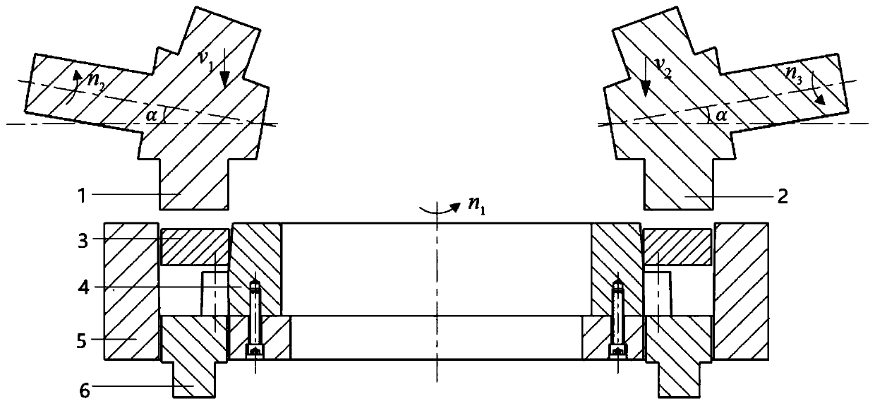
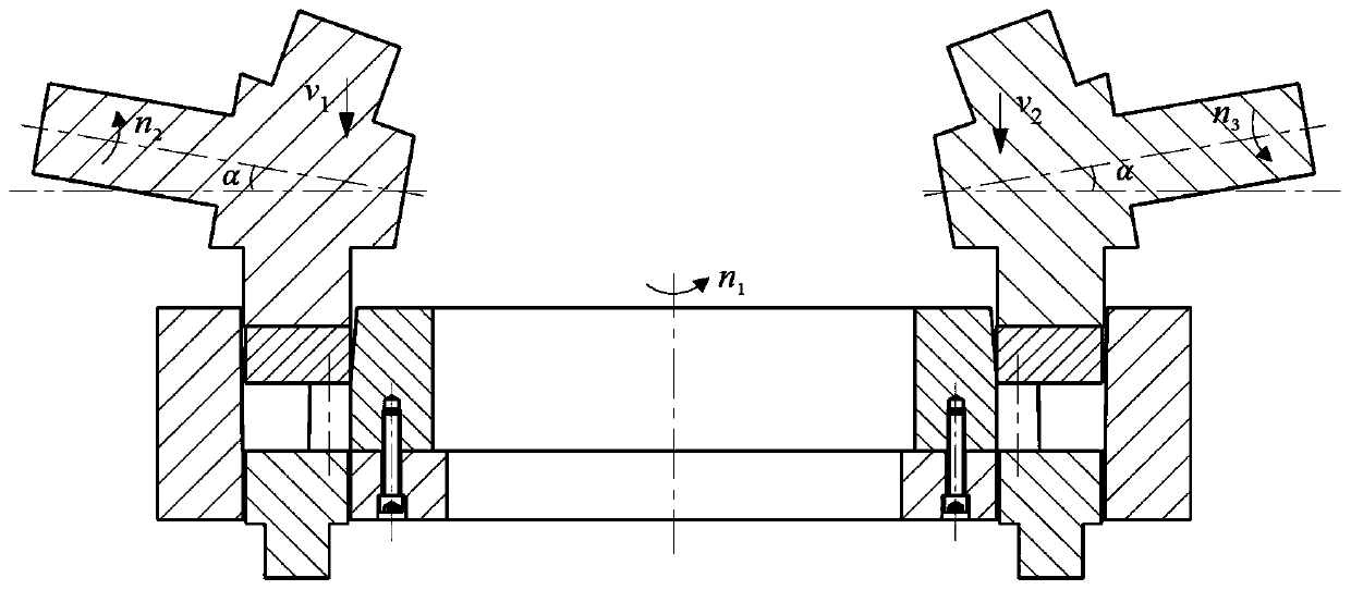
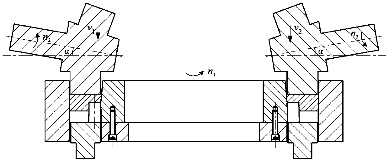
[0033] The split constrained rolling forming method of the large cylindrical gear ring of the present invention includes the following steps:
[0034] (1) Put the radially and axially rolled rectangular cross-section ring blank 3 directly into the constrained die composed of the toothed die 4 and the L-shaped die 5. Because the rolled large ring blank 3 has a large shape tolerance, The lower end surface of the rectangular section ring blank 3 has a certain distance from the upper end surface of the tooth profile. The restraint mold drives the rectangular section ring blank 3 around the central axis at a speed of n 1 At the same time, a pair of symmetrically arranged tapered rollers located on the outside of the restraining mold move to the top of the rectangular section ring blank 3 in the radial direction of the restraining mold (such as figure 1 Shown), the first cone roller 1 rotates at n 2 It rotates at a constant speed around its own axis, and the second cone roller 2 rotates at a speed of n 3 It rotates at a constant speed around its own axis, and the rotation direction of the two is opposite. Both the first cone roller 1 and the second cone roller 2 make a linear feed motion vertically downward at a speed v, and at the same time, they retreat in the radial direction of the restraining mold respectively, and press the ring blank 3 to the upper end surface of the tooth mold 4 (such as figure 2 Shown).
[0035] (2) The ring blank 3 is constrained by the constraining die in the radial direction and the position of the lower end surface. Under the continuous partial squeezing action of the first cone roller 1 and the second cone roller 2 on the upper end surface, the metal gradually moves toward the tooth profile of the constraining die. Flow in the cavity (e.g. image 3 Shown) until the tooth profile is completely filled (as Figure 4 Shown). After forming, the constraining mold and the cone roller stop rotating, the first cone roller 1 and the second cone roller 2 move vertically upwards above the upper end surface of the constraining mold, and then retreat to the initial position in the radial direction away from the constraining mold. At this time, the ejector rod 6 moves vertically upward to eject the formed part.
[0036] (3) Forging design. The large cylindrical gear in this example is a large cylindrical gear with internal teeth, with a module of 25mm, a number of teeth of 40, a tooth width of 98mm, and a pressure angle of 20° (such as Figure 5 Shown). Add 1mm margin and 1° inclination in the tooth profile part and tooth width direction of the large internal toothed cylindrical gear, and add 1mm margin to the outer wall position, and design a 2mm thick flash on the upper end to obtain forgings (such as Image 6 Shown).
[0037] (4) Ring blank 3 design with rectangular section. In step (1), for the large cylindrical gear with internal teeth, the outer diameter of the rectangular section ring blank 3 is less than the outer diameter of the forging by 5 mm, which is 1242 mm. The inner diameter and height of the rectangular cross-section ring blank 3 are determined by finite element simulation. The inner diameter is 925mm and the height is 83mm to ensure that the rectangular cross-section ring blank 3 is not unstable and can be completely filled during the forming process (such as Figure 7 Shown). The rectangular cross-section ring blank 3 needs to be heated to 1200° C. and coated with lubricant before being put into the constraining mold.
[0038] (5) In step (1), the constraining mold is composed of two parts, the tooth-shaped mold 4 and the L-shaped mold 5. The tooth-shaped mold 4 is fixed on the L-shaped mold 5 by 8 screws evenly distributed in the circumferential direction, and the rotation of the entire constrained mold is realized by the rotation of the L-shaped mold 5 around the central axis. Before the rectangular cross-section ring blank 3 is put into the restraint mold cavity, both parts of the restraint mold need to be preheated at 250°C and coated with lubricant.
[0039] (6) In step (1), the tooth mold 4 is a revolving entity divided into two parts. The lower part of the tooth-shaped die 4 forms the tooth-shaped part of the forging. The shape of this part matches the shape of the tooth-shaped part of the forging in step (2). The height of this part is equal to the width of the forging tooth, which is 100mm; the upper part has a 3° cone. Angle, height 110mm, restrict the flow of flash in the radial direction. For large cylindrical gears with internal teeth, the outer diameter of this part is smaller than the diameter of the addendum circle of the forging. The diameter of the lower end face is 937mm and the diameter of the upper end face is 918mm. 8 threaded holes are evenly distributed along the circumferential direction on the lower end surface of the toothed mold 4 for assembling with the L-shaped mold 5.
[0040] (7) Step (1) The L-shaped mold 5 is a ring with an L-shaped section. For a large cylindrical gear with internal teeth, the L-shaped horizontal part is in the direction of the inner diameter of the upright part, and the inner diameter of the L-shaped upright part is the same as in step (2) The outer diameter of the forgings is equal to 1252mm, and the inner diameter of the horizontal part is 660mm. The horizontal part of the L-shaped mold 5 corresponds to the position where the toothed mold 4 is placed with 8 through holes in the circumferential direction, corresponding to the position of the threaded hole of the toothed mold 4; the corresponding forging position is evenly distributed with 4 belts in the circumferential direction Toothed sector-shaped through holes are used to install the ejector rod 6, each through hole includes 3 tooth shapes, and the tooth shape matches the forging tooth shape in step (2).
[0041] (8) In step (1), the cone roller is composed of three parts, namely the base cone part 102, the forming part 103 and the clamping part 101. The angle α between the cone roller axis and the horizontal plane is 10°. Cone roller forming part 103 matches the upper end surface of the forging; when the cone roller reaches the maximum feed rate, the base cone part is 5mm higher than the upper end surface of the restraining die; the clamping part 101 is a cylinder with a diameter of 135mm, which is convenient for the roller mechanism to clamp the cone roller . Before the cone roller starts to move, the cone roller needs to be preheated to 250°C and coated with lubricant.
[0042] (9) In step (1), the ejector rod 6 is a fan-shaped member with teeth, and each ejector rod 6 includes 3 tooth shapes, which is the same as the number of the L-shaped mold 5 ejector rod 6 through the hole contains the tooth shape. correspond. The tooth shape of the ejector rod 6 is completely matched with the tooth shape of the target gear. For a large cylindrical gear with internal teeth, the outer diameter of the sector part is 2 mm smaller than the outer diameter of the forging in step (2).
[0043] (10) In step (1), the first cone roller 1 and the second cone roller 2 respectively rotate around their own axes, and the rotation speed of the two is the same, and the rotation direction is opposite. Speed of constrained mode n 1 =5r/min, the distance from a point on the upper end of the forging to the axis of the constraining die is r=548mm, and the distance from the vertex of the cone roller to the axis of the constraining die is e=220mm. Rotation speed of the first cone roller 1 n 2 , The speed of the second cone roller 2 n 3 Obtained by equation (1).
[0044]
[0045] The embodiments of the present invention are described above with reference to the accompanying drawings, but the present invention is not limited to the above-mentioned specific embodiments. The above-mentioned specific embodiments are only illustrative and not restrictive. Those of ordinary skill in the art are Under the enlightenment of the present invention, many forms can be made without departing from the purpose of the present invention and the protection scope of the claims, and these are all within the protection of the present invention.