
Control method of automatic welding production system of net rack connecting rods

An automatic welding and control method technology, applied in welding equipment, welding equipment, welding accessories, etc., can solve problems such as affecting product quality, inability to effectively control welding deformation, and affecting welding quality.

Active Publication Date: 2019-11-22
浩德重工科技(江苏)有限公司
View PDF10 Cites 6 Cited by
  • Summary
  • Abstract
  • Description
  • Claims
  • Application Information

AI Technical Summary

Problems solved by technology

[0005] 1. Although the pre-spot welding can be carried out by means of tooling positioning, there will still be spot welding deviations in the manual operation method, which cannot accurately ensure the coaxiality of the sealing plate or the through hole of the cone head and the steel pipe body, which will affect the product quality , It is easy to cause subsequent installation problems such as installation eccentricity and eccentric load on the grid connecting rod;
[0006] 2. Although the welding is carried out on the basis of pre-spot welding, the welding of the circular weld, even if the welding method is assisted by tooling, manual welding is usually difficult to ensure the uniformity of the weld, and thus cannot effectively control the welding deformation. control;
[0007] 3. The way of manual operation has high requirements on the skills and proficiency of personnel. During the welding process of circular welds, welding interruptions will inevitably occur, which intensifies the degree of welding deformation, and human factors such as the operator's emotions also affect the welding quality. influence

Method used


Image

  • Control method of automatic welding production system of net rack connecting rods
  • Control method of automatic welding production system of net rack connecting rods
  • Control method of automatic welding production system of net rack connecting rods

Examples


Embodiment Construction

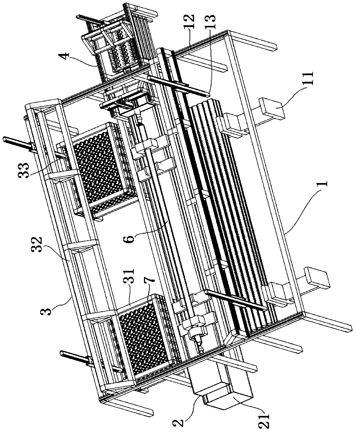
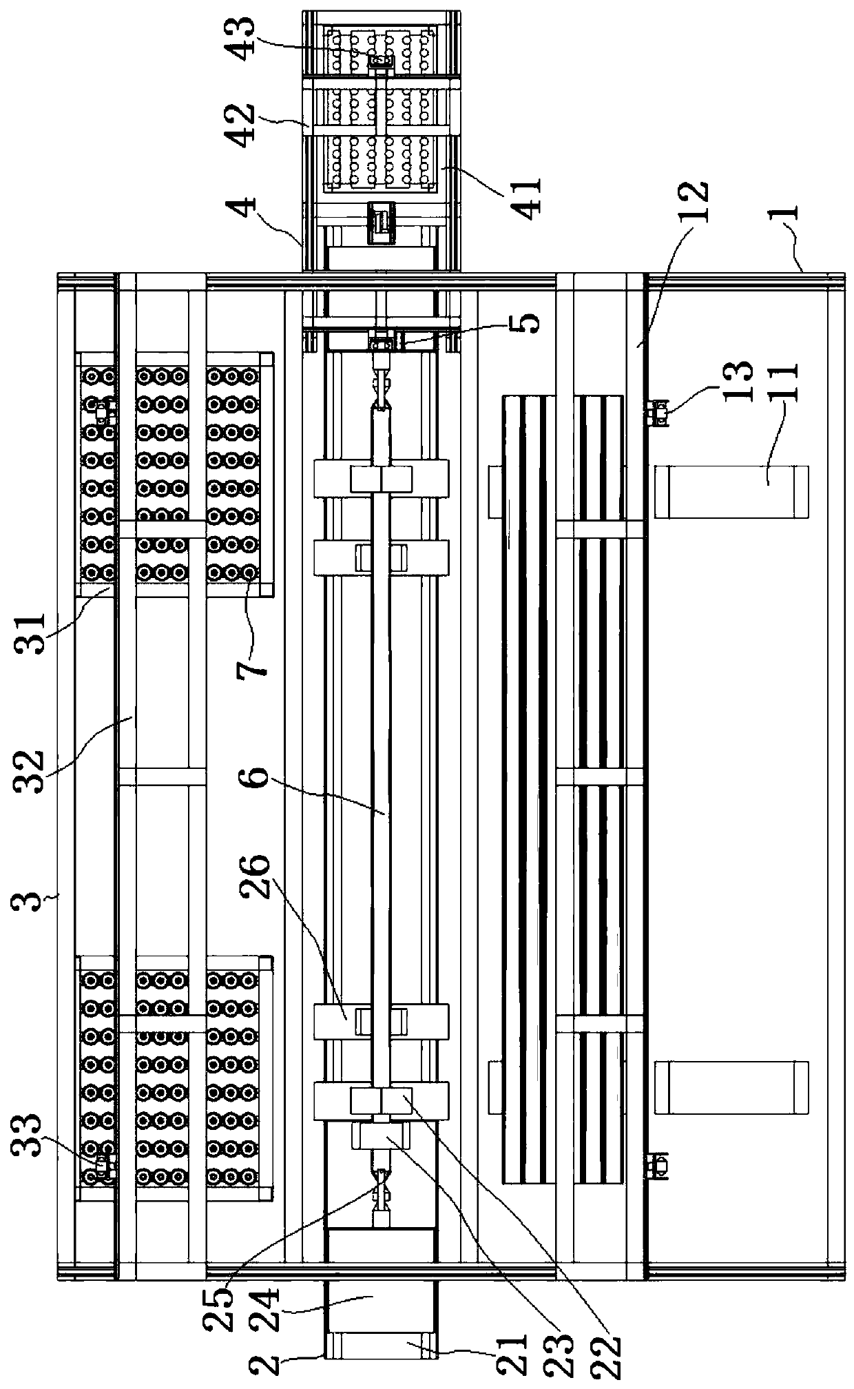
[0059] The grid connecting rod automatic welding production system is a digital control system, which can be seamlessly connected with the digital bus of the digital factory to realize centralized digital management. The present invention will be further described below in conjunction with the accompanying drawings (below, the length direction of the steel pipe workpiece 6 is described as the left-right direction).

[0060] Such as figure 1 , figure 2 As shown, the grid connecting rod automatic welding production system includes a steel pipe loading and unloading unit 1, an automatic welding unit 2, a sealing plate or cone head supply unit 3, an automatic bolt insertion unit 4 and a centralized electric control unit.

[0061] The steel pipe upper and lower line unit 1 is set at a set position within the range around the automatic welding unit 2, such as figure 2 As shown, the steel pipe loading and unloading unit 1 is arranged directly behind the automatic welding unit 2, ...


PUM


Abstract

The invention discloses a control method of an automatic welding production system of net rack connecting rods. The control method includes the steps of steel pipe line delivering, automatic welding,finished product line releasing and the like. Accurate coordinate grabbing and stacking of steel pipe workpieces can be achieved through a steel pipe line delivering unit and a steel pipe line releasing unit, accurate axial positioning of the steel pipe workpieces can be achieved through steel pipe radial clamping and positioning devices, bolts can be subjected to accurate coordinate grabbing andput in the ends of the steel pipe workpieces before welding through an automatic bolt implanting unit, accurate coordinate grabbing and coordinate positioning and connecting of sealing plate or cone head workpieces can be achieved through a sealing plate or cone head supply unit, the sealing plate or cone head workpieces can be accurately and coaxially coordinate-positioned at the welding ends ofthe steel pipe workpieces through sealing plate or cone head pushing devices, through cooperative work of steel pipe rotation drive devices and welding gun devices, one-time welding forming of complete annular weld joints can be achieved, and the control method is especially suitable for welding procedures of the net rack connecting rods.

Description

technical field [0001] The invention relates to a control method for an automatic welding production system, in particular to a control method for a production system suitable for automatic welding of grid connecting rod workpieces, and belongs to the technical field of grid connecting rod manufacturing. Background technique [0002] The grid structure is a space structure with a large span covered by connecting multiple grid connecting rods through nodes in a certain grid form. The grid structure has the advantages of good integrity, large space rigidity, and stable structure. Not only is it light in weight , The on-site construction workload is small, the construction speed is fast, and the height of the grid structure is small, which can effectively use the space, so it is widely used in the construction industry. [0003] The grid structure nodes made of steel mainly include cross-plate nodes, welded hollow ball nodes and bolt ball nodes. The grid structure composed of ...

Claims


Application Information

Patent Timeline
IPC IPC(8): B23K9/00B23K9/32B23K9/12B23K37/053
CPCB23K9/0026B23K9/12B23K9/32B23K37/053B23K37/0538
Inventor 郝新浦
Owner 浩德重工科技(江苏)有限公司
Learn More