
Waste gas recirculating system of engine

A technology of recirculation system and engine, which is applied in the direction of exhaust gas recirculation, engine components, combustion engine, etc., and can solve problems such as engine flameout

Pending Publication Date: 2019-11-22
GUANGDONG UNIV OF TECH
View PDF0 Cites 0 Cited by
  • Summary
  • Abstract
  • Description
  • Claims
  • Application Information

AI Technical Summary

Problems solved by technology

[0003] The purpose of this application is to provide an engine exhaust gas recirculation system to solve the problem that the water film or liquid droplets from water condensation are blown into the cylinder and cause the engine to stall

Method used


Image

  • Waste gas recirculating system of engine
  • Waste gas recirculating system of engine

Examples


Embodiment Construction

[0029] The technical solutions of the present application will be clearly and completely described below in conjunction with the accompanying drawings. Apparently, the described embodiments are some of the embodiments of the present application, not all of them. Based on the embodiments in this application, all other embodiments obtained by persons of ordinary skill in the art without making creative efforts belong to the scope of protection of this application.

[0030] In the description of this application, it should be noted that the terms "center", "upper", "lower", "left", "right", "vertical", "horizontal", "inner", "outer" etc. The indicated orientation or positional relationship is based on the orientation or positional relationship shown in the drawings, and is only for the convenience of describing the present application and simplifying the description, rather than indicating or implying that the referred device or element must have a specific orientation, use a spec...


PUM


Abstract

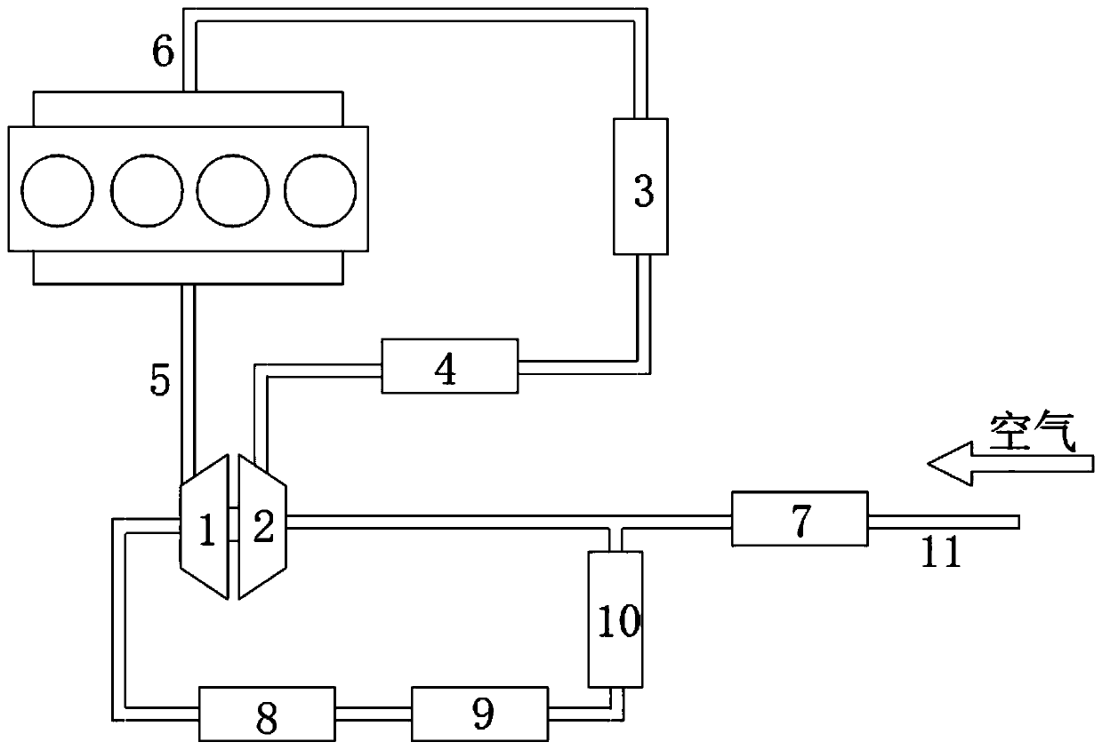
The invention discloses a waste gas recirculating system of an engine. The waste gas recirculating system is characterized by comprising a waste gas turbocharger, an air inflow pipe, an intercooler and a moisture absorber; the waste gas turbocharger comprises a turbine and a gas compressor; a waste gas inlet of the turbine is connected with an exhaust manifold of the engine; after a waste gas outlet of the turbine is connected with the air inflow pipe, the waste gas outlet is connected with a mixed gas inlet of the gas compressor; and after a mixed gas outlet of the gas compressor is sequentially connected with the moisture absorber and the intercooler, the mixed gas outlet is connected with an inflow manifold of the engine. According to the system, the moisture absorber is arranged in a waste gas circulating loop, water vapor is removed from mixed gas, the mixed gas is dehumidified into a dry state, and the problem that water films or liquid drops from water condensation are blown into an air cylinder, so that the engine flames out is solved.

Description

technical field [0001] The present application relates to the technical field of engines, in particular to an exhaust gas recirculation system of an engine. Background technique [0002] The supercharged engine runs at a high speed through the exhaust gas discharged from the engine, which drives the coaxial compressor to rotate at a high speed, and forcibly presses the supercharged air into the cylinder. In order to delay the combustion process and thereby reduce the generation of harmful emissions, it is common practice to introduce part of the exhaust gas produced by the engine back to the intake side to mix with fresh air, that is, Exhaust Gas Recirculation. The temperature of the mixed gas increases after being compressed, which not only affects the charging efficiency, but also tends to cause deflagration, so an intercooler is usually placed after the supercharger for cooling. The well-combusted exhaust gas contains a large amount of water vapor. As the temperature dr...

Claims


Application Information

Patent Timeline
IPC IPC(8): F02M26/35F02M26/22F01N3/02F01N3/035F02B29/04F02M35/02F02M35/024F02M35/10
CPCF02M26/35F02M26/22F01N3/02F01N3/035F02B29/04F02M35/02F02M35/024F02M35/10157F02M35/10222F02M35/10393Y02T10/12
Inventor 纪佳圳熊锐
Owner GUANGDONG UNIV OF TECH
Learn More