Modular design method for fir-shaped blade root blade groove of turbine of gas turbine

A modular design, gas turbine technology, applied in mechanical equipment, computing, engine components, etc., can solve problems such as long design cycle, gas turbine failure, stress concentration at tenon joints, etc., to reduce the number of selection iterations and improve design efficiency , The effect of short design cycle

Pending Publication Date: 2019-11-22
HANGZHOU TURBINE POWER GRP
View PDF3 Cites 1 Cited by
  • Summary
  • Abstract
  • Description
  • Claims
  • Application Information

AI Technical Summary

Problems solved by technology

Since the blade root and groove structure is subjected to complex loads including blade centrifugal force, thermal stress, aerodynamic force, vibration, and fretting wear, and because the radius of the transition arc between the tenon and teeth is small, very serious stress concentration occurs at the tenon joint. Phenomenon, so unreasonable mortise joint structure often causes gas turbine failure
The domestic design of blade root and groove structure is currently mostly based on the traditional manual selection and modeling design method, but this design method has a long period of time, and the design results lack certain reliability, which needs to be verified by experiments
At the same time, due to the lack of a perfect design method, standardized design cannot be realized, and the corresponding blade root slot structure cannot be selected according to different loads and working conditions

Method used


Image

  • Modular design method for fir-shaped blade root blade groove of turbine of gas turbine
  • Modular design method for fir-shaped blade root blade groove of turbine of gas turbine
  • Modular design method for fir-shaped blade root blade groove of turbine of gas turbine

Examples


Embodiment

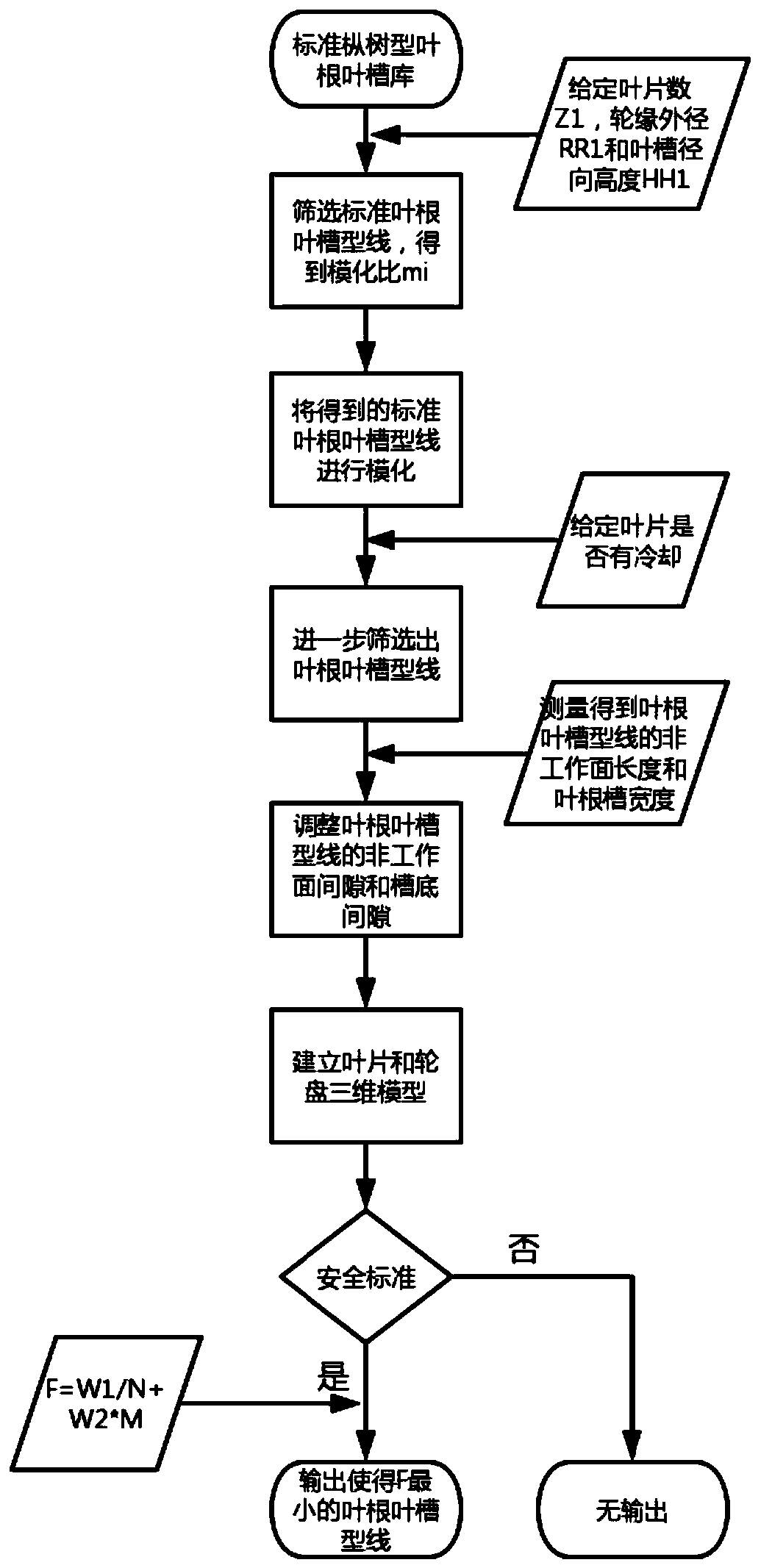
[0041] Such as Figure 1-3 Shown is a modular design method of fir-tree-shaped blade root and groove of a gas turbine turbine, which establishes a standard fir-tree-shaped blade-root and groove library, which includes the standards that have been applied to mature units The blade root groove shape line has 3-5 teeth, the tooth pitch is 7.135mm-12.475mm, and the wedge angle is 40°. All standard blade root groove shape lines are stored in the CAD drawing. Include the following steps:

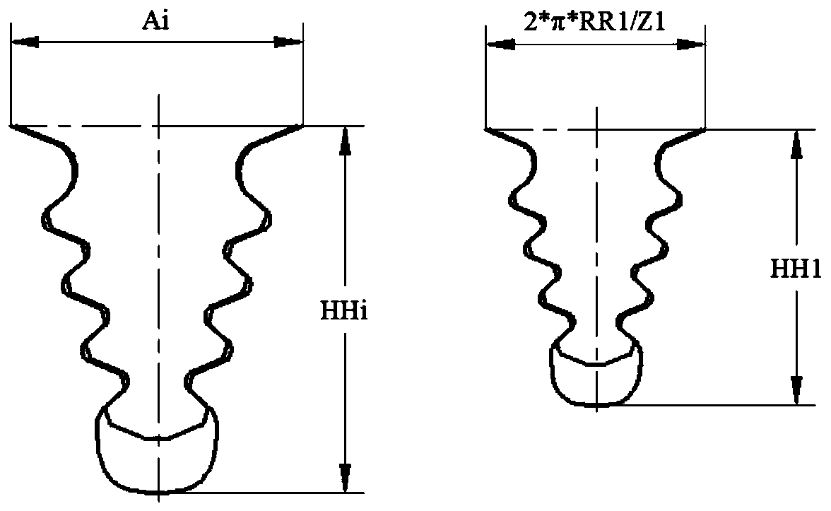
[0042] S1: given the number of blades Z1, the outer diameter of the rim RR1 and the radial height of the groove HH1, each standard blade root groove profile has a standard blade root top pitch Ai and a standard blade groove radial height HHi, calculate formula:

[0043] (2*π*RR1 / (Z1*HH1)):(Ai / HHi)

[0044] Among them, the formula for calculating the pitch at the top of the blade root is 2*π*RR1 / Z1. Screen out the standard blade root groove shape line that makes the value of the formula 0.9-1.1...


PUM


Abstract

The invention discloses a modular design method for a fir-shaped blade root blade groove of a turbine of a gas turbine, and relates to the fir-shaped blade root blade groove of the turbine of the gasturbine. The method comprises the following steps: establishing a standard fir-shaped blade root and blade groove library; screening out a standard blade root and blade groove profile from a standardfir tree type blade root and blade groove library; modeling the screened standard blade root and blade groove profile; further screening out a blade root and blade groove profile according to geometric constraint conditions; adjusting a non-working surface gap and a groove bottom gap of a blade root blade groove profile; establishing a three-dimensional model of the turbine blade and the wheel disc of the gas turbine, setting a safety standard, outputting a blade root and blade groove profile meeting the safety standard, and if no blade root and blade groove profile meeting the safety standardexists, not outputting; and giving an objective function, and outputting a blade root and blade groove profile which enables the objective function to be minimum. Standardized design of the blade root and blade groove structure is achieved; and the design method is short in design period, and the obtained blade root and blade groove structure has high reliability.

Description

technical field [0001] The invention relates to a gas turbine turbine fir tree blade root slot, in particular to a gas turbine turbine fir tree blade root slot modular design method. Background technique [0002] The fir tree blade root slot structure has the advantages of reasonable material utilization, large bearing area, small circumferential size and easy disassembly and assembly, so this connection form is generally used in the connection of gas turbine blade discs. Because the blade root groove structure is subjected to complex loads including blade centrifugal force, thermal stress, aerodynamic force, vibration, and fretting wear, and because the radius of the transition arc between the teeth is small, very serious stress concentration occurs at the tenon joint. Phenomenon, so unreasonable mortise and tenon structure often causes gas turbine failure. The domestic design of the blade root slot structure is currently mostly based on the traditional manual selection an...

Claims


Application Information

Patent Timeline
IPC IPC(8): G06F17/50F01D5/34
CPCF01D5/34
Inventor 魏佳明蓝吉兵吴宏超隋永枫周灵敏朱子奇谢健余沛坰
Owner HANGZHOU TURBINE POWER GRP
Why Eureka
Try Eureka