Ultrathin half-wall short-circuit circular polarization top end radiation antenna

A radiating antenna, circular polarization technology, applied in the direction of electrical short antenna, antenna, resonant antenna, etc., can solve the problems of complex structure, low efficiency of single-layer short-circuit wall patch antenna, etc. Effect

Active Publication Date: 2019-11-22
西安利芯电子科技有限公司
View PDF10 Cites 7 Cited by
  • Summary
  • Abstract
  • Description
  • Claims
  • Application Information

AI Technical Summary

Problems solved by technology

[0005] The technical problem to be solved by the present invention is to provide an ultra-thin half-wall short-circuit circularly polarized top radiating antenna to solve the problem of single-layer short-circuit wall in the case of single-point feeding proposed in the above-mentioned background technology. Patch antennas have problems such as low efficiency and complex structure

Method used


Image

  • Ultrathin half-wall short-circuit circular polarization top end radiation antenna
  • Ultrathin half-wall short-circuit circular polarization top end radiation antenna
  • Ultrathin half-wall short-circuit circular polarization top end radiation antenna

Examples


Embodiment 1

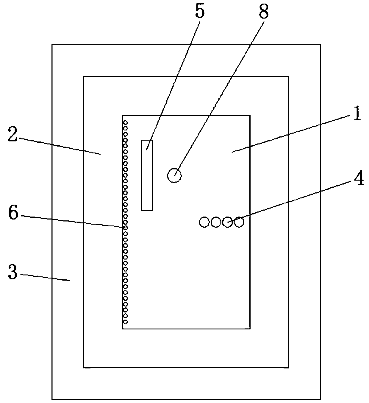
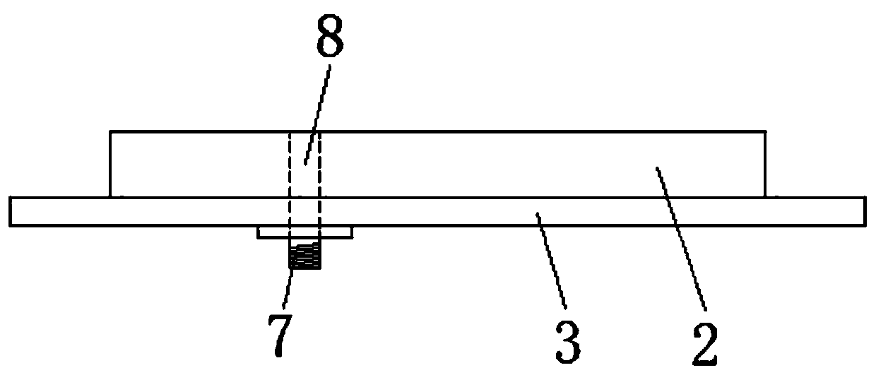
[0026] Example 1, such as figure 1 and figure 2 As shown, the present invention provides a technical solution: an ultra-thin half-wall short-circuit circularly polarized top radiation antenna, including a rectangular radiation microstrip patch 1, a dielectric substrate 2, a metal bottom plate 3, a first metal short-circuit pin 4 and a radio frequency connector 7. The rectangular radiating microstrip patch 1 is attached to one side of the dielectric substrate 2, wherein the rectangular radiating microstrip patch 1 is manufactured by a printed circuit process, the length of the rectangular radiating microstrip patch 1 is 0.46λ, and the width is 0.23 λ, printed on the dielectric substrate 2, and at the same time, on the side of the rectangular radiation microstrip patch 1 away from the radiation gap, a through hole for passing through the coaxial probe 7 is punched, and the rectangular radiation microstrip is fed through the coaxial probe 7. Patch 1 feeding; Rectangular radiati...

Embodiment 2

[0031] Embodiment 2, the application effect of the present invention will be described in detail below in conjunction with simulation.

[0032] 1. Simulation content

[0033] Please refer to Figure 3 to Figure 7 . The port reflection coefficient, antenna pattern and gain of the antenna in Embodiment 1 are simulated by using simulation software.

[0034] 2. Simulation results

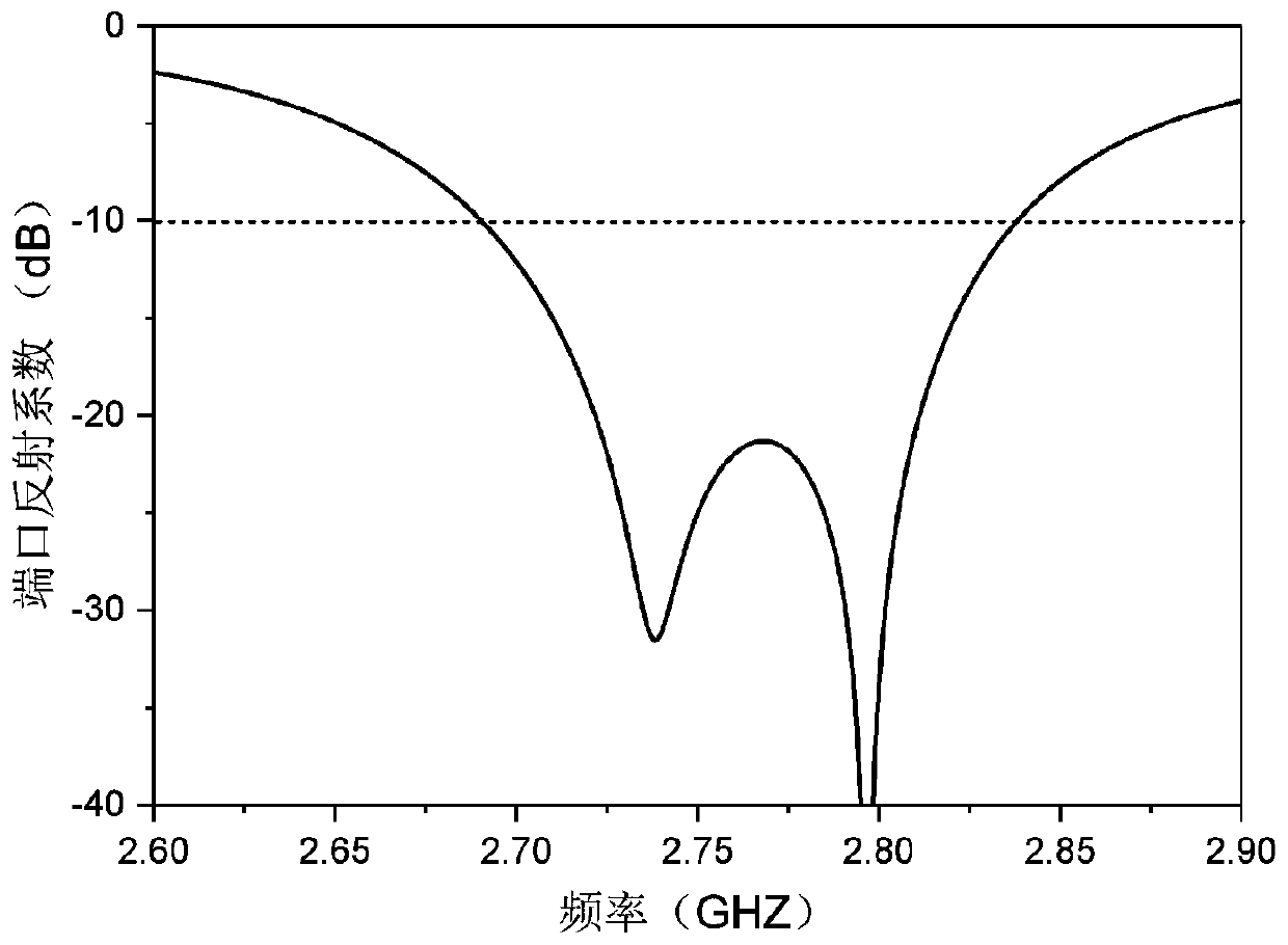
[0035] image 3 It is the reflection coefficient graph of the ultra-thin half-wall short circuit circular polarization top radiation antenna port of the present invention, Figure 4 It is the axial ratio curve diagram of the ultra-thin half-wall short-circuit circularly polarized top radiation antenna of the present invention. It can be seen that the frequency band whose port reflection coefficient is lower than -10dB is 2.69GHz-2.84GHz, accounting for 5.4%, and the 3dB axial ratio bandwidth is 2.76 GHz—2.80GHz, accounting for 1.4%. The characteristics of the circular polarization of the antenna a...


PUM


Abstract

The invention provides an ultrathin half-wall short-circuit circularly polarized top radiating antenna. The antenna comprises a rectangular radiation microstrip patch, a dielectric substrate, a metalbottom plate, four first metal short-circuit pins and a radio frequency connector, wherein the rectangular radiation microstrip patch is attached to one side surface of the dielectric substrate. The other side surface of the dielectric substrate is fixedly connected with the metal bottom plate; the four first metal short-circuit pins penetrate through the rectangular radiation microstrip patch, the dielectric substrate and the metal bottom plate and are connected with the metal bottom plate. The radio frequency connector is installed on the other side, opposite to the dielectric substrate, ofthe metal bottom plate, and a coaxial probe in the radio frequency connector penetrates through the dielectric substrate to be connected with the rectangular radiation microstrip patch in a welded mode. The problems that a single-layer short-circuit wall patch antenna of an existing radiation antenna is low in efficiency, unstable in directional diagram and the like under the condition of single-point feeding are solved.

Description

technical field [0001] The invention belongs to the technical field of wireless communication antennas, and in particular relates to an ultra-thin half-wall short-circuit circularly polarized top radiation antenna. Background technique [0002] In recent years, with the popularization and application of satellite navigation systems, both military and civilian fields have put forward new requirements for satellite navigation antennas. Due to the relative movement between the satellite and the ground, in order to ensure that different places on the ground can receive satellite signals, circularly polarized antennas become the best option for satellite communications. Since the antenna is installed on the satellite, it is required to radiate from the top of the antenna to achieve unidirectional radiation to the ground. Patch antennas are widely used in wireless communication systems due to their light weight, small size, and easy conformality. [0003] Traditional rectangul...

Claims


Application Information

Patent Timeline
Patent Type & Authority Applications(China)
IPC IPC(8): H01Q1/38H01Q1/50H01Q9/04
CPCH01Q1/38H01Q1/50H01Q9/0428
Inventor 刘能武郜森陈鑫鹏傅光祝雷
Owner 西安利芯电子科技有限公司
Why Eureka
Try Eureka