Oil-water separation and recovery device for catering industry

A technology of oil-water separation and recovery equipment, which is applied in separation methods, filtration separation, liquid separation, etc. It can solve problems such as poor oil-water separation effect, environmental sanitation impact, and inconvenient cleaning of pipeline blockage, so as to save maintenance costs and prolong the cleaning cycle Effect

Active Publication Date: 2019-11-26
乐清市川嘉电气科技有限公司
View PDF5 Cites 7 Cited by
  • Summary
  • Abstract
  • Description
  • Claims
  • Application Information

AI Technical Summary

Problems solved by technology

However, the traditional grease trap has the following obvious disadvantages: poor oil-water separation effect; civil construction is required, which is not only troublesome, but also takes up land and affects environmental sanitation (waste oil is mostly collected from grease traps with irregular design and poor environmental conditions ), it is inconvenient to clean the pipe blockage, and the cost of use and maintenance is relatively high
However, its working principle has not made much progress compared with the grease trap. It is simply standing and stratifying. The sewage needs to be pumped by a pump, and the residue in the original sewage needs to be manually opened

Method used


Image

  • Oil-water separation and recovery device for catering industry
  • Oil-water separation and recovery device for catering industry
  • Oil-water separation and recovery device for catering industry

Examples


Embodiment Construction

[0036] The following will clearly and completely describe the technical solutions in the embodiments of the present invention with reference to the accompanying drawings in the embodiments of the present invention. Obviously, the described embodiments are only some, not all, embodiments of the present invention. Based on the embodiments of the present invention, all other embodiments obtained by persons of ordinary skill in the art without making creative efforts belong to the protection scope of the present invention.

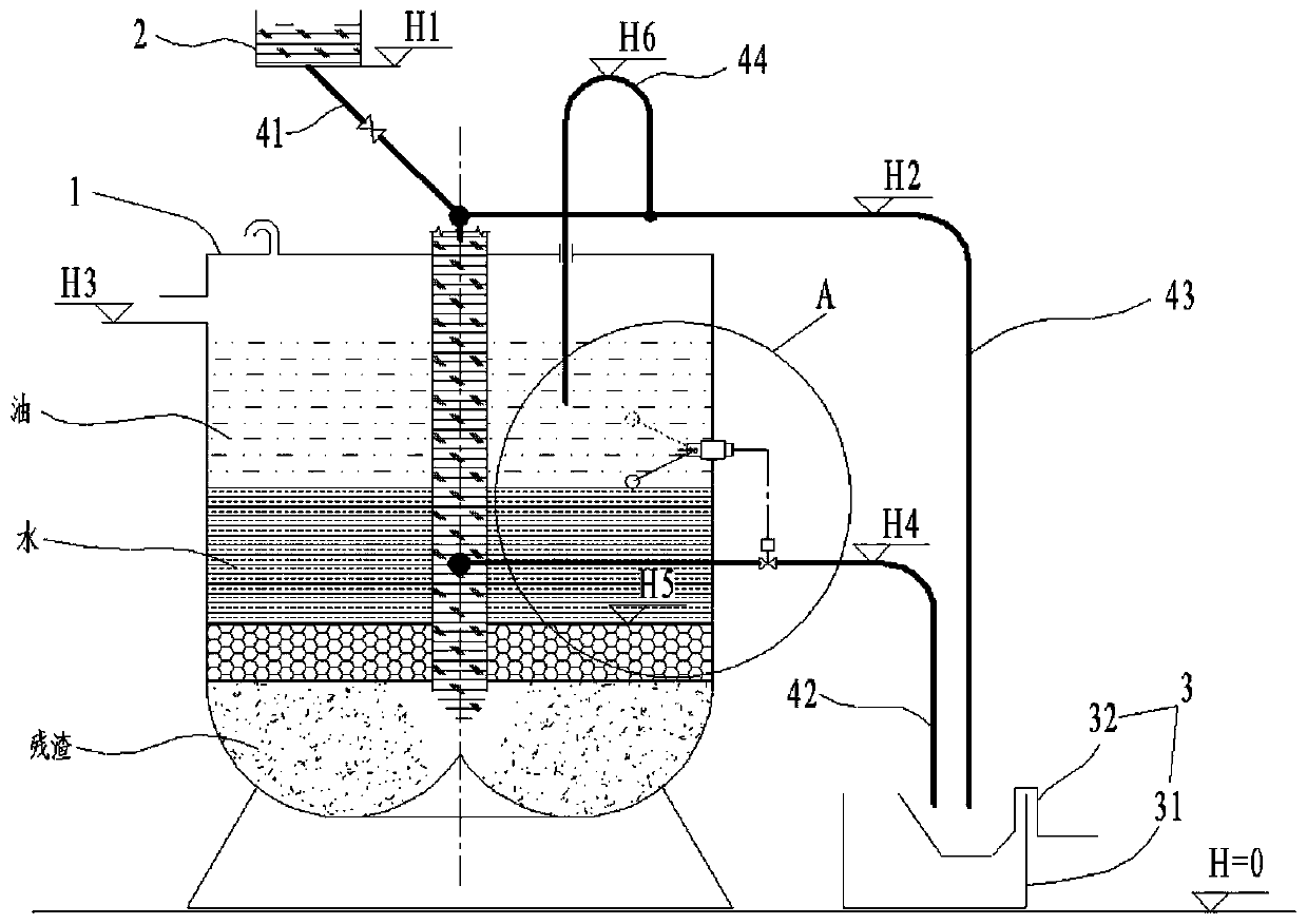
[0037] Such as figure 1 As shown, a kind of oil-water separation and recovery equipment for the catering industry includes an oil separation tank 1, a feed box 2, and a discharge tank 3. The oil separation tank 1 is connected to the feed box 2 and the discharge tank 3 respectively through pipelines. Above, the feed box 2 is higher than the oil trap 1, and the oil trap 1 is higher than the discharge tank 3.

[0038] The oily sewage discharged from the kitchen ...


PUM


Abstract

The invention discloses an oil-water separation and recovery device for the catering industry. The device comprises an oil separation tank, a feeding box and a discharge tank, the oil separation tankis respectively connected with the feeding box and the discharge tank through pipelines, the feeding box is higher than the oil separation tank, and the oil separation tank is higher than the discharge tank. The oil separation tank comprises a tank body, a core tube and a filter layer, the filter layer is arranged at the lower part in the tank body, and divides the internal of the tank body into an oil water cavity and a water inlet cavity, the side surface of the upper part of the oil water cavity is provided with an oil discharge port, and the top of the oil water cavity is provided with a gas discharge port; the core tube is inserted into the tank body from top to bottom, the lower end of the core tube is located in the water inlet cavity, the top of the core tube is connected with a downcomer and a siphon tube respectively, the other end of the downcomer is connected with the feeding box, the other end of the siphon tube is connected to the discharge tank, and the highest point ofthe siphon tube is lower than the bottom of the feeding box and higher than the oil discharge port; and the oil-water separation and recovery device further comprises a blow-down tube, one end of theblow-down tube is inserted into the tank body, the other end is bent and then is connected to the highest point of the siphon tube, and the highest point of the blow-down tube is higher than the highest point of the siphon tube.

Description

technical field [0001] The invention relates to the field of environmental protection equipment, in particular to oil-water separation and recovery equipment for the catering industry. Background technique [0002] With the development of society, the scale and number of hotels, hotels and canteens are increasing day by day, and the amount of catering sewage produced thereupon is increasing. Catering sewage cannot be directly discharged to municipal sewage pipelines. Although the country has not yet given specific industry discharge standards, it is only using the three-level standard in the "Comprehensive Wastewater Discharge Standard" GB8978-1996: all sewage units, animal and vegetable oil in sewage Emissions shall not be higher than 100mg / L. [0003] At present, traditionally, grease traps are mostly used for degreasing catering sewage. The basic principle is to use the difference in specific gravity between oil and water. Under a certain residence time, the grease in se...

Claims


Application Information

Patent Timeline
IPC IPC(8): C02F1/40C02F9/02
CPCC02F1/40C02F1/001B01D36/008
Inventor 金一超
Owner 乐清市川嘉电气科技有限公司
Why Eureka
Try Eureka