A direct contact fluid ice slurry generator and its preparation method

A liquid ice and contact technology, which is applied in ice making, ice making, lighting and heating equipment, etc., can solve the problems that affect the ice making efficiency, water can not be in direct contact with the refrigerant, etc., to improve the contact area and contact Time, improve the efficiency of ice making, improve the effect of heat transfer efficiency

Active Publication Date: 2021-05-11
NORTH CHINA UNIV OF WATER RESOURCES & ELECTRIC POWER
View PDF11 Cites 1 Cited by
  • Summary
  • Abstract
  • Description
  • Claims
  • Application Information

AI Technical Summary

Problems solved by technology

[0005] The purpose of the present invention is to provide a direct contact fluid ice slurry generator to solve the problem that in the prior art, when the brine is passed into the water of the ice slurry generator, it is easy to cause part of the water not to be in direct contact with the brine Furthermore, the problem of affecting the ice-making efficiency; at the same time, the present invention also provides a direct-contact liquid ice slurry preparation method to solve the problem that in the prior art, when the brine is passed into water, some water cannot be mixed with the brine. Technical issues that directly contact and affect ice production efficiency

Method used


Image

  • A direct contact fluid ice slurry generator and its preparation method
  • A direct contact fluid ice slurry generator and its preparation method
  • A direct contact fluid ice slurry generator and its preparation method

Examples


Embodiment 1

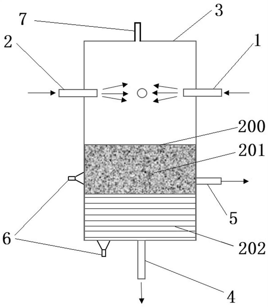
[0038]The structure of the preparation device in this embodiment is as figure 1 and figure 2 As shown, the production device includes an ice slurry production cylinder 3, the bottom of the ice slurry production cylinder 3 is provided with a lower fluid outlet 4 and an ice slurry outlet 5, and the brine and ice-making working medium are directly contacted in the ice slurry production cylinder. When producing ice slurry, the ice slurry floats lightly to form the upper ice slurry layer 201, and the rest of the fluids are mixed together to form the lower fluid layer 202 below, and the prepared ice slurry flows out through the ice slurry outlet 5 and enters the corresponding storage bin Among them, the lower layer fluid flows out through the lower layer fluid outlet 4 and is recycled.

[0039] A nozzle group 100 is provided on the circumferential wall of the ice slurry production cylinder 3, and the nozzle group 100 is located above the spray outlet 5, and the nozzle groups here ...

Embodiment 2

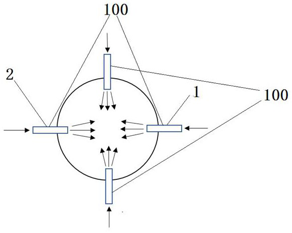
[0050] The structure of the direct contact type fluid ice slurry maker in embodiment 2 is as follows image 3 As shown, the structure of the fluid ice slurry extractor is basically the same as that of the ice slurry extractor in Example 1, the only difference being that in the ice slurry extractor 3 in Example 2, the nozzle group is along the ice slurry Two layers are arranged at intervals in the axial direction of the preparation cylinder 3 , and each layer is provided with a nozzle group, and each nozzle group includes a brine nozzle 1 and an ice-making working medium nozzle 2 . Moreover, in this embodiment, the two-layer nozzle groups are distributed in a staggered manner in the circumferential direction of the ice slurry production cylinder.

[0051] In other embodiments, the nozzle groups may be distributed in more than three layers at intervals along the axial direction of the ice slurry production cylinder. Of course, the brine nozzles and the ice-making working medium...

Embodiment 3

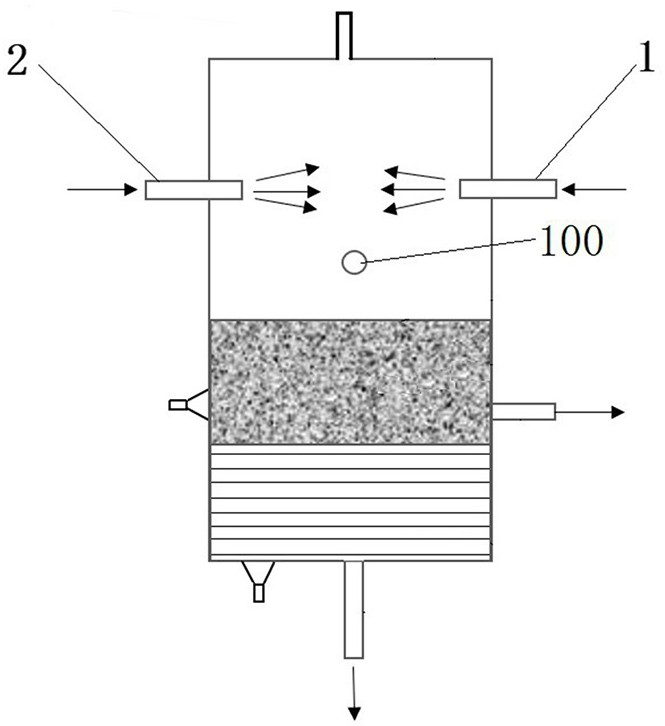
[0053] The structure of the direct contact type fluid ice slurry maker in embodiment 3 is as follows Figure 4 and Figure 5 As shown, the structure of the fluid ice slurry extractor is basically the same as that of the ice slurry extractor in Embodiment 1, the only difference being that only one group of nozzle groups is provided on the ice slurry extractor cylinder 3 in Embodiment 3 100. The nozzle group 100 includes a refrigerant nozzle 1 and an ice-making working medium nozzle 2, and the two nozzles need only be arranged facing each other.

[0054] In the above embodiments, the brine nozzle can be selected from a gaseous refrigerant or a liquid refrigerant according to actual needs, so as to meet the ice slurry preparation requirements under different conditions.

[0055] In the above-mentioned embodiments, when the direct-contact fluid ice slurry generator is in use, it needs to be connected with corresponding brine input pipelines, ice-making working medium input pipeli...


PUM


Abstract

The invention relates to a direct contact type fluid ice slurry generator and a preparation method. The direct contact fluid ice slurry generator includes an ice slurry extraction cylinder and a nozzle group, and the ice slurry extraction cylinder has an ice slurry outlet; The nozzle group includes a brine nozzle for spraying brine and an ice-making working medium nozzle for spraying ice-making working fluid, and both the brine nozzle and the ice-making working medium nozzle are arranged on the ice slurry making cylinder , the brine nozzle and the ice-making working medium nozzle are oppositely arranged so that the input brine and ice-making working medium collide; the brine nozzle and the ice-making working medium nozzle are located above the ice slurry outlet, so that the corresponding The nozzle is located above the ice slurry layer during operation. The brine sprayed by the corresponding nozzles collides with the ice-making working medium to increase the mixing degree of the two and improve the heat transfer efficiency. At the same time, during the mixing and collision process, the ice crystals will become smoother in shape and more uniform in size, which reduces the flow resistance of ice slurry, makes ice slurry have better fluidity, and reduces the transportation load.

Description

technical field [0001] The invention belongs to the technical field of preparation of fluid ice slurry, and in particular relates to a direct contact type fluid ice slurry generator and a preparation method. Background technique [0002] Fluid ice slurry is a mixture of fine ice crystal particles and aqueous solution. Its good fluidity, heat transfer, and energy storage properties make fluid ice slurry an ideal cold storage and transportation medium. It has shown great promise in many fields. It has unique advantages and is widely used. At present, the preparation methods of fluid ice slurry mainly include: scraping method, supercooled water method, vacuum method, fluidized bed method and direct contact method, etc. Among them, the direct contact method has the highest heat exchange efficiency, relatively low energy consumption, and Ice making equipment has simple structure, high safety, and is not easy to form ice blockage, so it is an ideal ice slurry preparation technolo...

Claims


Application Information

Patent Timeline
Patent Type & Authority Patents(China)
IPC IPC(8): F25C1/00
CPCF25C1/00Y02P60/85
Inventor 高玉国阿古斯·萨斯弥多秦朝举郭朋彦
Owner NORTH CHINA UNIV OF WATER RESOURCES & ELECTRIC POWER
Why Eureka
Try Eureka