Pneumatic transformer fault oil drainage system

A technology for transformer failure and pneumatic oil discharge, which is applied in the direction of transformer/inductor cooling, fluid pressure actuators, servo motor components, etc. problems, achieving the effect of no maintenance, improved system reliability, and quick start-up

Pending Publication Date: 2019-11-26
孙铭阳
View PDF0 Cites 2 Cited by
  • Summary
  • Abstract
  • Description
  • Claims
  • Application Information

AI Technical Summary

Problems solved by technology

However, in the design of current equipment and substations in operation on the grid, the emergency oil discharge pipeline of the transformer is opened by manual gate valves and manually broken glass seals.
When the transformer is at risk of burning, the operator has to risk his life to open the valve and break the glass. If the transformer has burned, it is usually impossible to discharge oil, and the transformer can only be burned and exploded.
In order to solve this risk problem, the transformer management unit has adopted the method of leading the transformer oil discharge pipeline to the other side of the firewall to set up a valve to reduce the risk of opening the valve when the transformer burns, but there is still no reliable solution for the glass sealing plate at the entrance of the oil storage tank. control break
In addition, the current oil discharge and nitrogen injection system used in the power grid system also has problems such as poor operation reliability and high risk of misoperation due to the fact that the actuators are mostly mechanical interlocking and electronic control. Discharge the transformer oil directly after starting, causing accidents and having a huge impact

Method used


Image

  • Pneumatic transformer fault oil drainage system
  • Pneumatic transformer fault oil drainage system
  • Pneumatic transformer fault oil drainage system

Examples


Embodiment 1

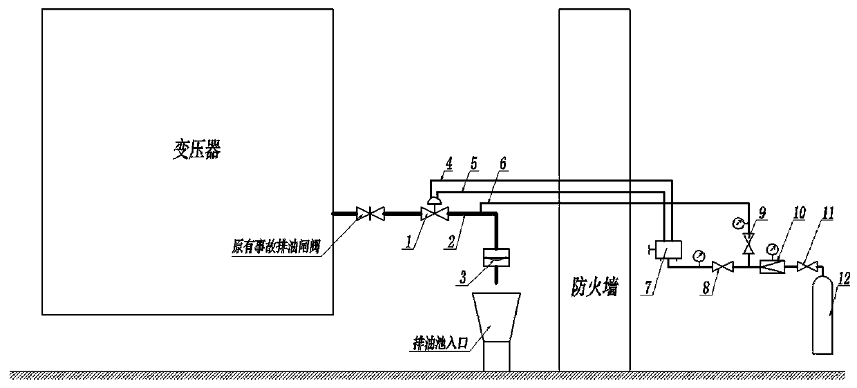
[0034] Such as figure 1 As shown, the oil outlet of the original accident oil drain gate valve of the transformer is connected to the pneumatic oil drain valve 1, the outlet of the pneumatic oil valve 1 is connected to the component pipeline 2 and the bursting disc 3, and the outlet of the bursting disc 3 enters the underground oil discharge through the pipeline Pool; set the air inlet on the component pipeline 2 and connect the bursting disc opening control pipeline 6 to the pneumatic control system; the control part of the pneumatic oil drain valve 1 connects the oil discharge opening control pipeline 4 and the oil discharge closing control pipeline 5 to Pneumatic control system. The pneumatic control system consists of a bursting disc opening control valve 9, an oil discharge control valve 8, a reversing valve 7, a pressure reducing valve 10, an air source main valve 11, an air source 12, pipelines and pressure gauges and is installed in the pneumatic control cabinet . The ...

Embodiment 2

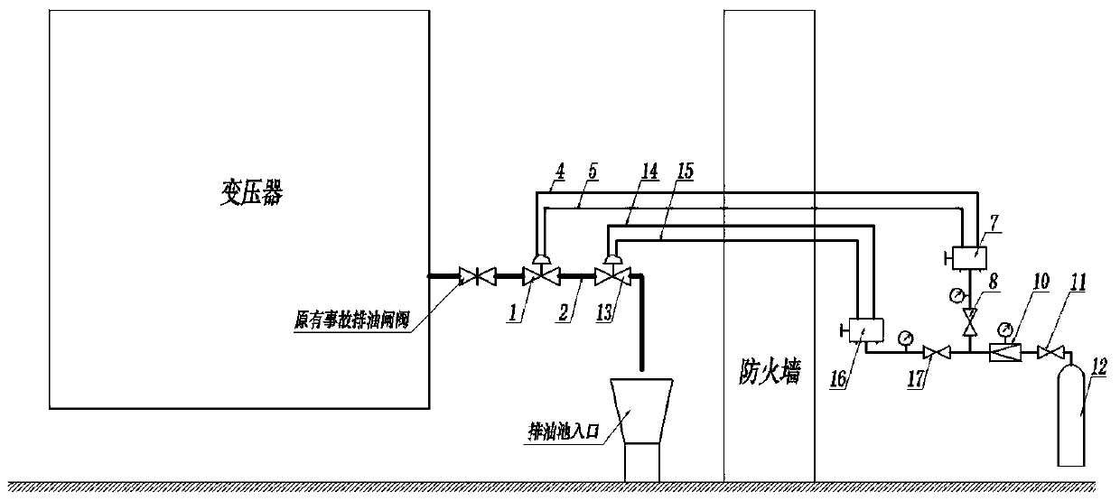
[0040] Such as figure 2 As shown, the outlet of the original accident drain gate valve of the transformer is connected with two series-connected pneumatic drain valve 1 and pneumatic sealing valve 13. The latter one can have the same specifications as the previous one, and its function is to seal the second time. The outlet is connected to the inlet of the underground oil drain tank; the control parts of the pneumatic oil drain valve 1 and the pneumatic sealing valve 13 have pipelines connected to the pneumatic control cabinet, and the valve is opened by pneumatic drive. After installation, the pneumatic oil drain valve 1 and the pneumatic sealing valve 13 are both in the closed state, and the sealing reversing valve 16 leads to the sealing opening control line 14; after vacuuming or filling and exhausting the front line of the pneumatic oil drain valve (1) , Open the original accident oil drain gate valve of the transformer, the transformer insulating oil flows in and is seale...

Embodiment 3

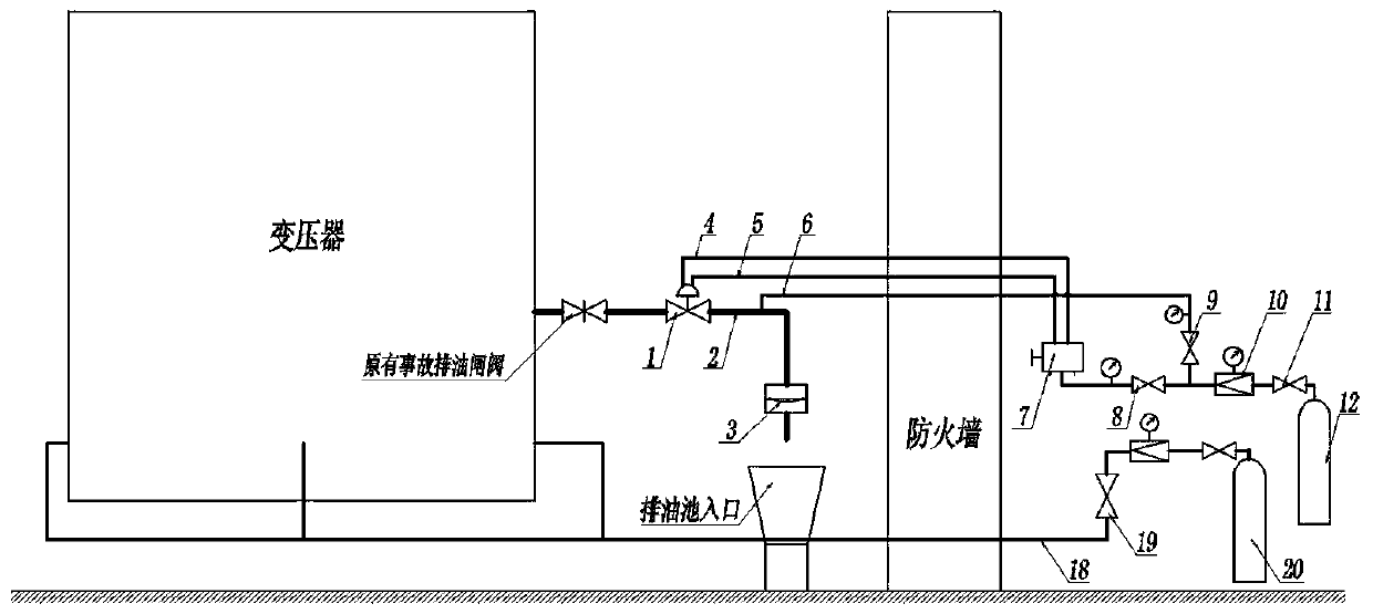
[0043] Such as image 3 As shown, on the basis of the technical solutions of the first or second embodiment, a flame-retardant gas pipeline 18 communicating with the inside of the oil tank is evenly distributed around the transformer, and the flame-retardant gas pipeline is connected to a flame-retardant gas cylinder 20 through a valve 19 and a pressure reducing valve. , The flame retardant gas can be nitrogen, carbon dioxide or other inert gases. When the transformer has a serious fault and needs to drain oil, when the pneumatic oil drain device is turned on, the flame-retardant gas pipeline valve 19 is opened to realize the flame-retardant gas enters the transformer.


PUM


Abstract

The invention relates to a pneumatic opening scheme of a transformer fault oil drainage pipeline. A pneumatic valve, a bursting disc assembly and a pneumatic control system are included; when a transformer has a serious fault and needs to drain oil, a bursting disc is opened at first through the pneumatic control system; then, the pneumatic valve is opened; remote manual or electric transformer oil drainage in a security area is realized; simultaneously, the pneumatic control system can open the pneumatic valve arranged on a flame retardant gas pipeline so as to inject flame retardant gas intothe transformer; therefore, fire protection and fire fighting are realized; simultaneously, oil conservator cut-off and directional oil drainage also can be realized; meanwhile, necessary conditionsof light detection and pressure detection of transformer fault oil drainage and nitrogen injection are increased; and the scheme solves the problems that the existing equipment cannot perform securityoil drainage when the transformer is dangerous, the existing oil drainage and nitrogen injection system is unreliable to start and the like.

Description

Technical field [0001] The invention relates to a pneumatic oil drain system for transformer failure, which belongs to the field of power equipment safety. Background technique [0002] According to the power system specifications, when a major failure occurs in a large-scale transformer and there is a risk of combustion, the insulating oil inside the transformer should be quickly discharged to the accident oil storage tank. However, in the current network operation equipment and substation design, the accident drain pipeline of the transformer is opened by manual gate valve and manually broken glass sealing sheet to open the accident drain. When the transformer is at risk of burning, the operator has to risk his life to open the valve and break the glass. If the transformer is already burning, it is usually no longer possible to discharge oil, and the transformer can only be burned and exploded. In order to solve this risk problem, the transformer management unit adopted a valv...

Claims


Application Information

Patent Timeline
Patent Type & Authority Applications(China)
IPC IPC(8): H01F27/14F15B13/02
CPCF15B13/025H01F27/14
Inventor 孙艺夫王金帅郭思聪李鹏雁
Owner 孙铭阳
Why Eureka
Try Eureka