Bulk acoustic wave filter and electronic equipment

A bulk acoustic wave filter, main body technology, applied in electrical components, impedance networks, etc., to achieve the effect of improving out-of-band suppression and offsetting adverse effects

Pending Publication Date: 2019-11-26
TIANJIN UNIV +1
View PDF8 Cites 8 Cited by
  • Summary
  • Abstract
  • Description
  • Claims
  • Application Information

AI Technical Summary

Problems solved by technology

However, as the size of the chip decreases day by day, the limit

Method used


Image

  • Bulk acoustic wave filter and electronic equipment
  • Bulk acoustic wave filter and electronic equipment
  • Bulk acoustic wave filter and electronic equipment

Examples


Embodiment 1

[0039] This embodiment provides a bulk acoustic wave filter with improved near-stop band suppression, and the sealing ring is connected to the reference ground plane of the carrier board through a metal ball, thereby eliminating the coupling between each resonator and between each resonator and the sealing ring , thereby improving near-stop-band rejection.

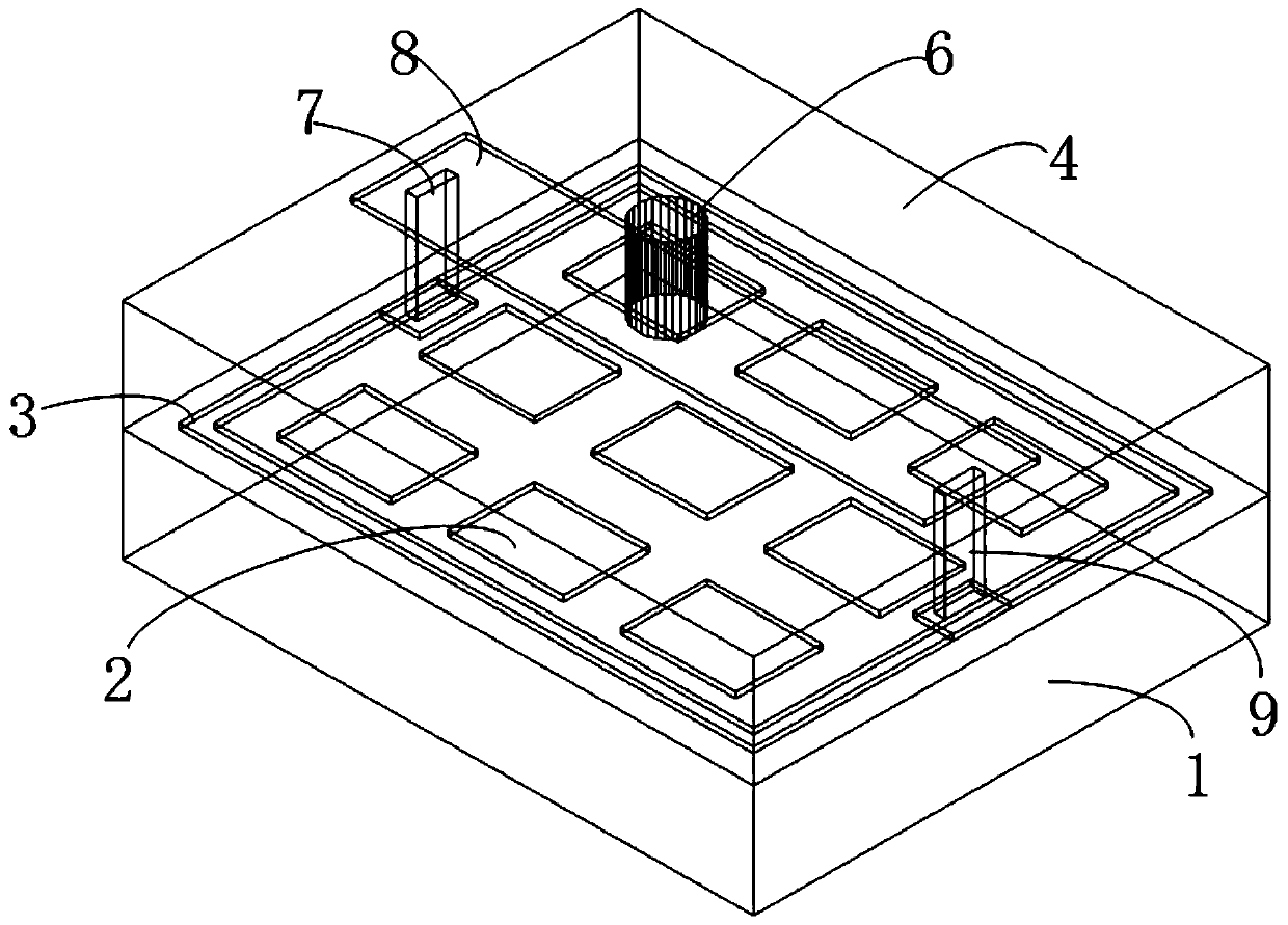
[0040] Please refer to the attached image 3 , the bulk acoustic wave filter includes:

[0041] chip body 1;

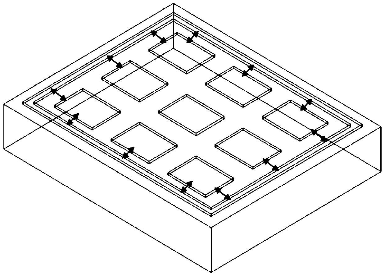
[0042] A plurality of resonators 2 are sequentially arranged on the surface layer of the chip main body 1, and the periphery of the resonators 2 is surrounded by a sealing ring 3;

[0043] The protective cap 4 is arranged on the chip main body 1, and the two sides of the sealing ring 3 are respectively connected to the surface layer of the protective cap 4 through the first metal post 7 and the second metal post 9, between the first metal post 7 and the second metal post 9 connected by a metal strip 8;

[0044...

Embodiment 2

[0054] This embodiment provides a bulk acoustic wave filter, please refer to the attached Image 6 , the bulk acoustic wave filter includes a chip main body 1 , a protective cap 4 and a carrier plate 5 .

[0055] The chip body 1 is arranged on a silicon substrate; a plurality of resonators 2 are arranged in sequence on the chip body 1, and the periphery of the plurality of resonators 2 is surrounded by a sealing ring 3, and the two sides of the sealing ring 3 pass through the first metal pillar 7 and the second metal post 9 are connected to the surface of the protective cap 4, the first metal post 7 and the second metal post 9 are respectively connected to metal strips 8, and the two metal strips 8 are respectively connected to the ground plane of the carrier board through metal balls.

[0056] In this embodiment, the internal resonator 2 is jointly protected by the protective cap 4 connected with the sealing ring 3 .

[0057] In the bulk acoustic wave filter proposed in this...

Embodiment 3

[0059] This embodiment provides a bulk acoustic wave filter, please refer to the attached Figure 7 , the bulk acoustic wave filter includes a chip main body 1 , a protective cap 4 and a carrier plate 5 .

[0060] The chip body 1 is disposed on a silicon substrate; a plurality of resonators 2 are arranged in sequence on the chip body 1, and the periphery of the plurality of resonators 2 is surrounded by a sealing ring 3, and one side of the sealing ring 3 passes through the first metal pillar 7 is connected to the surface of the protective cap 4 , the first metal post 7 is connected to a metal strip 8 , and the metal strip 8 is connected to the ground plane of the carrier board 5 through the metal ball 6 .

[0061] In this embodiment, the internal resonator 2 is jointly protected by the protective cap 4 connected with the sealing ring 3 .

[0062] In the bulk acoustic wave filter proposed in this embodiment, one side of the sealing ring 3 is connected to the surface layer of ...


PUM


Abstract

According to the bulk acoustic wave filter capable of improving near-stop band suppression and the electronic equipment. Sealing rings are connected to the reference ground plane of the carrier platethrough the solder balls, so that coupling between the resonators and coupling between the resonators and the sealing rings are eliminated, and near-stop band suppression is further improved. The bulkacoustic wave filter comprises a chip main body, a protective cap and a carrier plate, wherein a plurality of resonators are sequentially arranged on the surface layer of the chip main body, and a sealing ring is arranged at the periphery of the plurality of resonators; the protective cap is arranged on the chip main body, the two sides of the sealing ring are respectively connected with a metalcolumn, the bottom ends of the two metal columns are respectively connected with the sealing ring, the top ends of the two metal columns penetrate through the surface layer of the protective cap to beconnected with a metal strip, and the metal strip is connected with the carrier plate through metal balls.

Description

technical field [0001] The invention relates to the technical field of bulk acoustic wave filters, in particular to a bulk acoustic wave filter and electronic equipment for improving near-stop band suppression. Background technique [0002] With the increasing speed, miniaturization and integration of radio frequency signal processing chips, the problems of electrical suppression and isolation in chips have become more and more prominent, and have become important factors affecting the electrical performance of chips. [0003] In order to make the device more miniaturized, the interval between each resonator is further reduced; the periphery of the resonator is protected by a metal sealing ring to prevent gas, liquid, etc. from contaminating the chip, and the interval between each resonator and the sealing ring is also further reduced; the spacing is reduced The small size leads to the parasitic capacitance of the resonators coupled with each other through the sealing ring, ...

Claims


Application Information

Patent Timeline
IPC IPC(8): H03H9/02H03H9/205
CPCH03H9/02047H03H9/02125H03H9/02118H03H9/205
Inventor 庞慰梁新红
Owner TIANJIN UNIV
Why Eureka
Try Eureka