
Circulation air chamber for plant cultivation room

A culture room and circulating air technology, applied in plant cultivation, botanical equipment and methods, cultivation and other directions, can solve the problems of uneven growth environment, low space utilization, complex overall structure, etc., to avoid drying and water loss , to avoid heat loss, to ensure the effect of full mixing

Pending Publication Date: 2019-12-03
FUJIAN PROV AGRI MACHANIZATION INST
View PDF0 Cites 1 Cited by
  • Summary
  • Abstract
  • Description
  • Claims
  • Application Information

AI Technical Summary

Problems solved by technology

[0003] At present, the air supply and induction circulation method generally relies on air conditioners or environmental machines with their own fans to promote the air circulation. However, the air outlets of these equipment are limited by the size of the equipment, and the positions of the air supply and return air are relatively concentrated. There is a large air supply dead angle
In addition, the wind is led to the surroundings by arranging air ducts, and even improved to a sandwich orifice structure. The sandwich plate is densely covered with micro-hole air nozzles. Although the wind circulation effect is improved, the overall structure is complicated and the space utilization rate is not high.
[0004] The traditional wind circulation method also needs to pay attention to the layout of the tuyere. The airflow near the tuyere is stronger, and the direct blowing generated by it will dry the medium or seedlings and lose water, resulting in uneven growth environment.
When carrying out scientific experiments with high requirements on environmental temperature and humidity, there will be more uncertain factors

Method used


Image

  • Circulation air chamber for plant cultivation room
  • Circulation air chamber for plant cultivation room
  • Circulation air chamber for plant cultivation room

Examples


Embodiment Construction

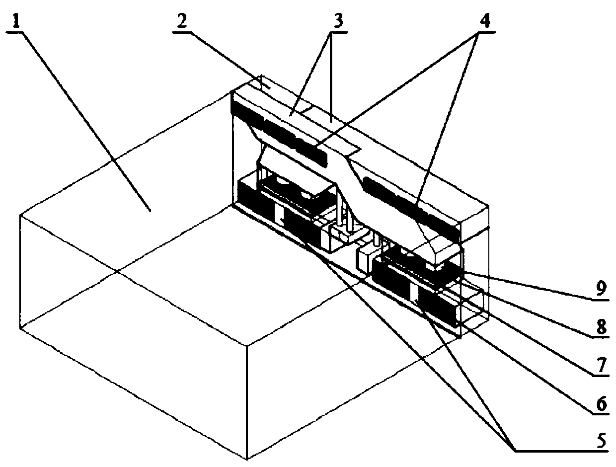
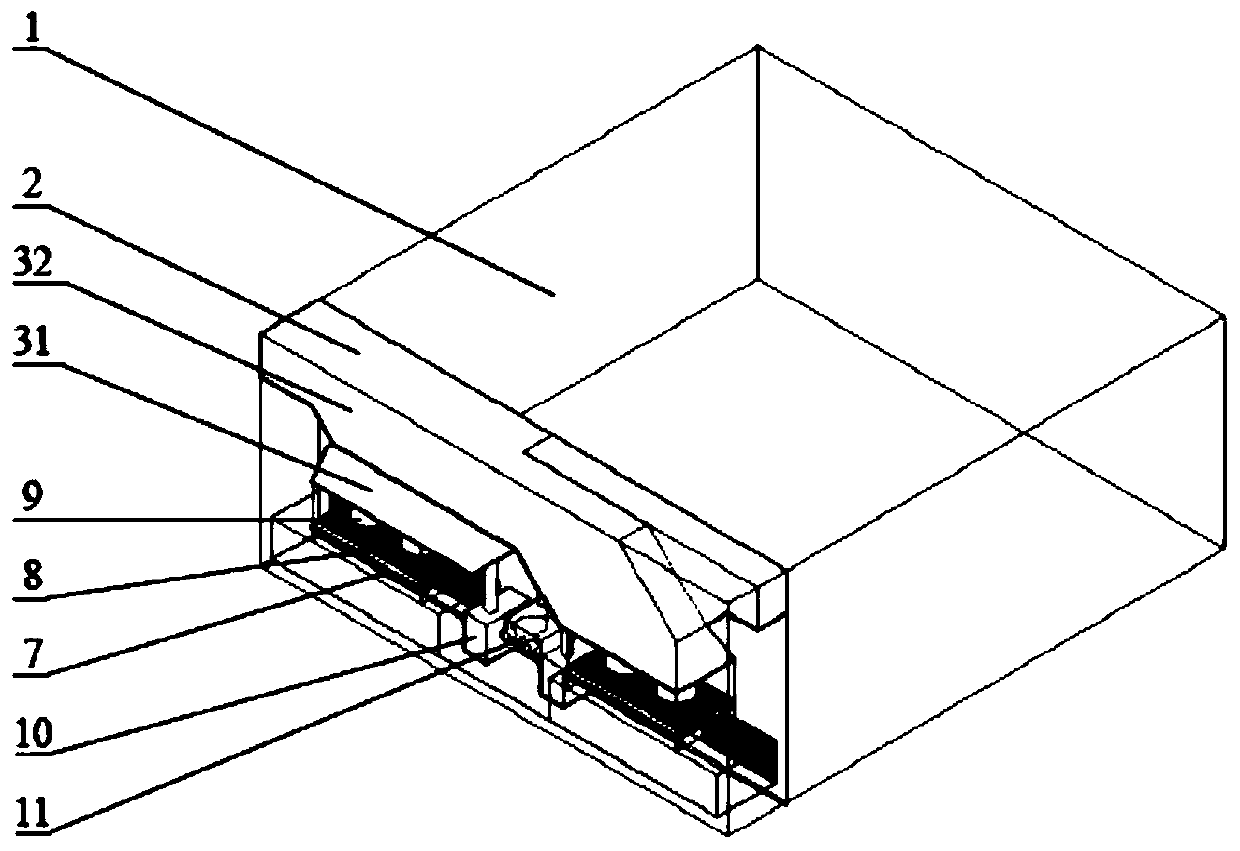
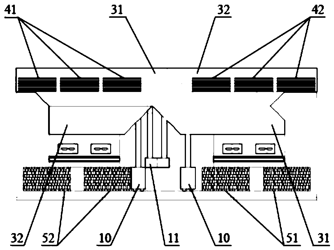
[0023] Such as figure 1 or figure 2 As shown, the circulation air chamber of the plant cultivation room of the present invention includes the air chamber 2 connected to the side of the plant cultivation chamber 1, and the air chamber 2 is provided with two mutually independent circulation air passages 3, and one end of each circulation air passage 3 is The air return port 5 is connected, and the other end of each circulating air duct 3 is connected with an air supply port 4, and each return air port 5 and air supply port 4 communicate with the inside of the plant cultivation room 1 respectively; the circulating air duct 3 is connected with a fan 9 inside.

[0024] The two circulating air ducts 3 intersect each other in space, and the air return port 5 and the air supply port 4 of the two circulating air ducts 3 are arranged in a cross on the side of the air supply and induction, intersecting up and down, left and right, the air supply port 4 and the return air port 5 The dis...


PUM


Abstract

The invention discloses a circulation air chamber for a plant cultivation room. The circulation air chamber comprises an air chamber connected to the side face of the plant cultivation room, wherein the air chamber is internally provided with two independent circulation air ducts; the two circulation air ducts cross with each other in space, and return air inlets and air supply outlets of the twocirculation air ducts are formed crosswise in an air blowing and an air drawing side face; the plant cultivation room is internally provided with a fresh air ventilator, wherein the fresh air ventilator is arranged outside the circulation air ducts, an indoor air supply outlet and indoor return air inlet of the fresh air ventilator are connected to the two circulation air ducts respectively, and an outdoor air inlet port and outdoor exhaust port of the fresh air ventilator are connected to the outer portion of the plant cultivation room respectively. In order to meet the requirements of the uniformity of the environment inside an artificial climate room, the unique design of crossed circulation air ducts is adopted, the two circulation air ducts which are not communicated with each other cross with each other in the space, and the air supply outlets and the return air inlets which are connected with the two circulation air ducts form a three-dimensional cross wind field in the indoor space, so that the air flow in the space is strengthened, and sufficient mixing of the indoor air is ensured.

Description

technical field [0001] The invention relates to the technical field of plant cultivation, in particular to a circulating air chamber of a plant cultivation chamber. Background technique [0002] The plant culture room is used in scientific experiments to study the influence of climate and environmental conditions on plant activities, and to provide an ideal growth environment for plant breeding, seedling cultivation and fungus cultivation. The indoor air temperature, humidity, CO2 concentration and other environmental parameters are adjusted through air conditioning, humidification and other equipment, and various climate and environmental conditions in the cultivation room are artificially simulated. The humid heat generated by these devices requires the circulation of forced air to promote the flow of indoor air, so as to achieve a uniform internal environment as soon as possible. [0003] At present, the air supply and induction circulation method generally relies on air...

Claims


Application Information

Patent Timeline
Patent Type & Authority Applications(China)
IPC IPC(8): A01G9/14A01G9/24A01G18/60A01G18/69
CPCA01G9/14A01G9/246A01G18/60A01G18/69Y02A40/25
Inventor 陈晓
Owner FUJIAN PROV AGRI MACHANIZATION INST
Learn More