
Pore plate type dielectric barrier discharging plasma generation device for waste gas treatment

A technology for dielectric barrier discharge and waste gas treatment, which is applied in the field of plasma, can solve the problems of restricting the use of dielectric barrier discharge plasma generating devices, affecting the popularization of dielectric barrier discharge plasma generating devices, and covering a large area of ​​the device, and achieves a simple structure. , easy to implement, and the effect of preventing creepage

Pending Publication Date: 2019-12-03
重庆新离子环境科技有限公司
View PDF0 Cites 0 Cited by
  • Summary
  • Abstract
  • Description
  • Claims
  • Application Information

AI Technical Summary

Problems solved by technology

Although the dielectric barrier plasma discharge technology has the advantages of clear principle and strong applicability, due to the very complicated multi-field coupling process such as flow field, temperature field and electromagnetic field in the plasma generation channel, the discharge area is prone to discharge concentration, Inhomogeneous and unstable conditions such as creepage seriously affect the application of dielectric barrier discharge plasma generators
The dielectric barrier discharge plasma generation device has a complex structure, each channel needs an independent power supply, and the discharge area in the channel is limited, resulting in a large area of ​​the device, complicated fabrication, and high cost
These problems not only seriously restrict the use of dielectric barrier discharge plasma generators in the waste gas treatment industry, but also affect the further promotion of dielectric barrier discharge plasma generators

Method used


Image

  • Pore plate type dielectric barrier discharging plasma generation device for waste gas treatment
  • Pore plate type dielectric barrier discharging plasma generation device for waste gas treatment
  • Pore plate type dielectric barrier discharging plasma generation device for waste gas treatment

Examples


specific Embodiment approach

[0028] It should be noted that the structures, proportions, sizes, etc. shown in the drawings attached to this specification are only used to match the content disclosed in the specification, for those who are familiar with this technology to understand and read, and are not used to limit the implementation of the present invention Any modification of the structure, change of the proportional relationship or adjustment of the size shall still fall within the scope of the technical content disclosed in the present invention without affecting the effect and purpose of the present invention. In the range.

[0029] At the same time, terms such as "upper", "lower", "left", "right", "middle" and "one" quoted in this specification are only for the convenience of description and are not used to limit this specification. The practicable scope of the invention and the change or adjustment of its relative relationship shall also be regarded as the practicable scope of the present inventi...

Embodiment 1

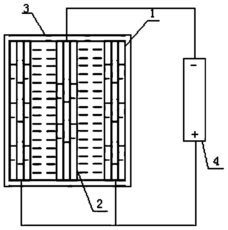
[0031] like figure 1 As shown, an orifice-plate dielectric barrier discharge plasma generating device for waste gas treatment includes a positive plate 1 and a negative plate 2. The positive plate 1 and the negative plate 2 both have an orifice structure, and the positive plate 1 and the negative plate 2. The misalignment of the openings on the 2.

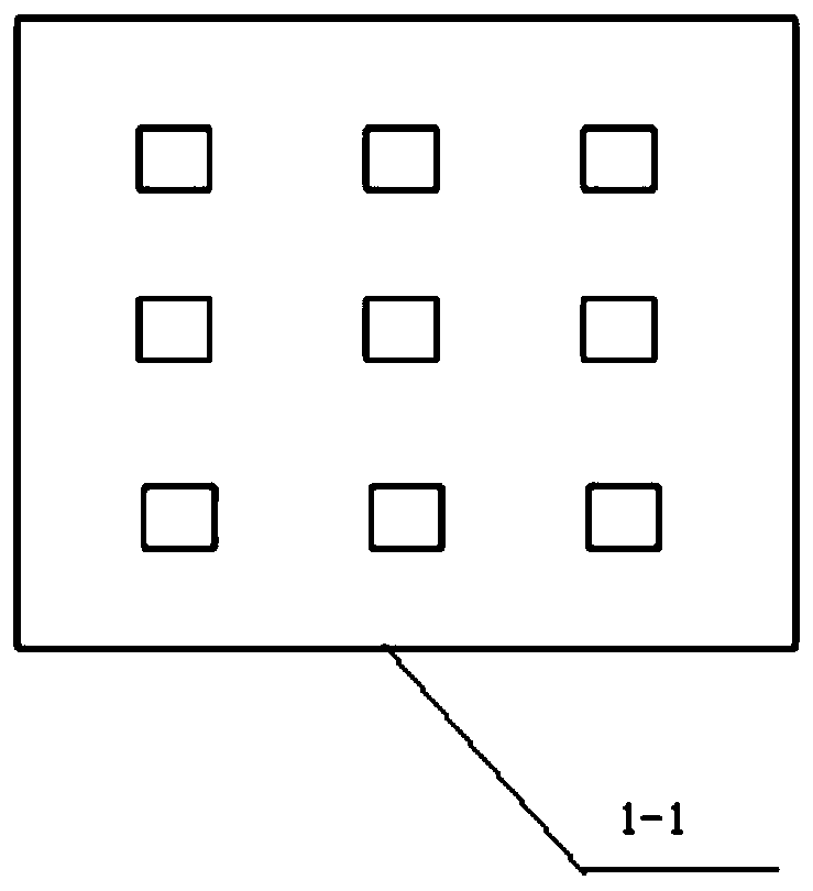
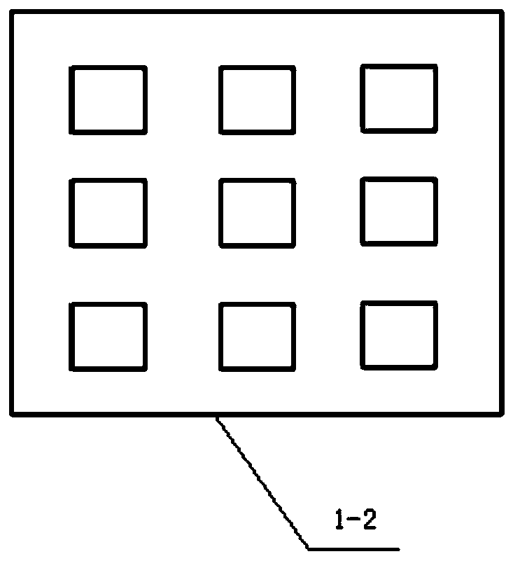
[0032] The positive plate 1 includes a first electrode plate 1-2 and at least two first dielectric plates 1-1, the first electrode plate 1-2 is located between the two first dielectric plates 1-1; the first dielectric The structural form of board 1-1 is as follows figure 2 As shown, it is made of alumina and other materials with high dielectric constant and good thermal conductivity. The first dielectric plate 1-1 is provided with a plurality of first through holes, and the first electrode plate 1-2 is provided with a plurality of second through holes, and the central axes of the plurality of second through holes are respectivel...


PUM


Abstract

The invention discloses a pore plate type dielectric barrier discharging plasma generation device for waste gas treatment. The device comprises positive pole plates and negative pole plates, wherein the positive pole plates and the negative pole plates are arranged alternately, the positive pole plates and the negative pole plates are each of a pore plate structure, and holes are formed in the positive pole plates and the negative pole plates in a staggered mode. With the pore plate type dielectric barrier discharging plasma generation device, the structure form of the dielectric barrier discharging plasma generation device is simplified, and the gas flow rate can be regulated by regulating the distance between the positive pole plates and the negative pole plates and the hole positions, so that operation is simple, and implementation is convenient.

Description

technical field [0001] The invention belongs to the technical field of gas discharge and discharge plasma, and in particular relates to an orifice-plate dielectric barrier discharge plasma generating device for waste gas treatment. Background technique [0002] With the sustained and rapid economic development and the acceleration of urbanization, the discharge of hazardous wastes is also increasing year by year, and the resulting waste treatment and disposal problems have become increasingly severe and urgent. Protecting the environment and reducing pollution has become the focus and topic of common concern all over the world. At the same time, it also promotes and promotes the development of new products and technologies in order to provide better solutions for waste treatment and disposal. In recent years, thermal plasma technology has begun to emerge in the field of harmless waste treatment, especially in the treatment of hazardous waste, which has unique advantages and ...

Claims


Application Information

Patent Timeline
Patent Type & Authority Applications(China)
IPC IPC(8): B01D53/32
CPCB01D53/32B01D2259/818
Inventor 王阳王卫民张百灵高岭惠晓晖陈小林李博陈威仰
Owner 重庆新离子环境科技有限公司
Learn More