
Scanning galvanometer type laser welding system

A technology of laser welding and scanning galvanometer, which is applied in the direction of laser welding equipment, welding equipment, metal processing equipment, etc., can solve the problems of increased welding difficulty, unsatisfactory spot welding speed, and inaccurate welding positioning, so as to improve spot welding Speed, good welding effect, accurate welding positioning effect

Inactive Publication Date: 2019-12-03
DONGGUAN UNIV OF TECH +1
View PDF8 Cites 7 Cited by
  • Summary
  • Abstract
  • Description
  • Claims
  • Application Information

AI Technical Summary

Problems solved by technology

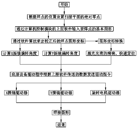
[0004] In the laser welding system, although the galvanometer scanning system has high quality in terms of scanning speed, scanning angle, scanning resolution, and scanning accuracy performance, when there are a large number of spot welding spots, the overall spot welding speed The speed reflects the level of the galvanometer scanning laser spot welding technology. Therefore, how to improve the overall spot welding speed is a goal pursued by the current galvanometer scanning laser spot welding technology; and the overall spot welding speed is determined by the laser. The output power of the laser beam, the beam quality of the laser beam, the spot size of the laser beam after focusing, the welding material and the selected flux, etc. The influence of welding speed is also very important; in addition, due to the scanning distortion of the galvanometer scanning system in the focal plane, the welding difficulty is increased, resulting in inaccurate welding positioning
[0005] The Chinese invention patent with the application number CN200810220533.5 describes the fiber laser dynamic focusing galvanometer scanning spot welding system and its welding method. The scanning is performed through the dynamic focusing unit composed of the fiber laser and the moving negative lens and focusing mirror. To a certain extent The welding speed and the scanning working range are improved; but when there are many spot welding spots, the overall spot welding speed of the invention is mainly determined by the output power of the laser, the beam quality of the laser beam, the spot size of the focused laser beam, The welding material and other factors are determined, and in the case of certain factors, the overall spot welding speed cannot meet

Method used


Image

  • Scanning galvanometer type laser welding system

Examples


Embodiment Construction

[0031] The technical solutions of the embodiments of the present invention will be clearly and completely described below with reference to the accompanying drawings. Obviously, the described embodiments are only a part of the embodiments of the present invention, rather than all the embodiments. Based on the embodiments of the present invention, All other embodiments obtained by those of ordinary skill in the art without creative work fall within the protection scope of the present invention.

[0032]The present invention will be further described in detail below through specific embodiments and in conjunction with the accompanying drawings.

[0033] A scanning galvanometer type laser welding system, comprising: a laser and an optical path module, a power supply module, a galvanometer scanning module, a computer control module, a workbench and a cooling module;

[0034] The laser and optical path module emits a laser beam through a laser, reflects and focuses the laser beam t...


PUM


Abstract

The invention discloses a scanning galvanometer type laser welding system which comprises a laser and light path module, a power module, a galvanometer scanning module, a computer control module, a workbench and a cooling module. A laser beam is irradiated to a welded workpiece through the laser and light path module. Adjustment of a welding circuit and pulse width frequency is achieved through the power module. The galvanometer scanning module is used for enabling focused light beams to form uniform scanning patterns on a scanning plane, the computer control module is used for controlling input of all parameters, welding scanning tracks and movement of the workbench, so workpiece fixing and welding temperature control in the welding process are achieved through the workbench and the cooling module. A scanning path is reasonably selected through computer software, so that the laser beam scans and welds more welding spots within the same time, and the overall spot welding speed is increased; besides, the laser beams are reflected and focused through a light path system, scanning distortion is overcome, welding positioning is more accurate, and the welding effect is better.

Description

technical field [0001] The invention relates to the field of laser welding, in particular to a scanning galvanometer type laser welding system. Background technique [0002] Laser is one of the most important inventions since the 20th century. The difference between it and traditional light characteristics is that the main emission of laser is stimulated radiation, so laser has the characteristics of high intensity, good unidirectionality and coherence, suitable for The processing of materials and distance measurement have great potential in their own technology. The rapid development of laser technology has played an important role in the development of the national economy and social progress; at present, it is widely used in electronics, metallurgy, automobiles and machinery manufacturing industries; laser scanning As a branch of laser technology, its application in the manufacturing field marks the birth of a new interdisciplinary and cross-industry science, and also for...

Claims


Application Information

Patent Timeline
Patent Type & Authority Applications(China)
IPC IPC(8): B23K26/082B23K26/22B23K26/70
CPCB23K26/22B23K26/082B23K26/702
Inventor 孙振忠朱宝华郭建文王瑾李小婷邓君路崧赵曙明王皓亮
Owner DONGGUAN UNIV OF TECH
Learn More