Thermoplastic plastic molding equipment based on electroluminescence principle

A thermoplastic and molding equipment technology, applied in the direction of coating, etc., can solve the problems of high-density layer thickness, large shrinkage and deformation of molded plastic products, and failure to achieve the desired shape, so as to achieve the effect of increasing temperature and reducing shrinkage rate

Active Publication Date: 2019-12-03
江苏具鑫包装科技有限公司
View PDF5 Cites 0 Cited by
  • Summary
  • Abstract
  • Description
  • Claims
  • Application Information

AI Technical Summary

Problems solved by technology

[0003] Among them, plastic molding is an essential step in the production of plastic materials. According to the characteristics of plastic parts, when the molten material contacts the outer layer of the cavity surface, it cools immediately to form a low-density solid shell, and due to the poor thermal conductivity of plastic, the plastic The inner layer of the part is cooled slowly to form a high-density solid layer with large shrinkage, resulting in wall thickness, slow cooling, and high-density layer thickness, which finally leads to large shrinkage and deformation of molded plastic products, and injection-molded items cannot achieve the desired shape. , so a thermoplastic molding equipment based on the principle of electroluminescence came into being

Method used


Image

  • Thermoplastic plastic molding equipment based on electroluminescence principle
  • Thermoplastic plastic molding equipment based on electroluminescence principle
  • Thermoplastic plastic molding equipment based on electroluminescence principle

Examples


Embodiment Construction

[0020] The following will clearly and completely describe the technical solutions in the embodiments of the present invention with reference to the accompanying drawings in the embodiments of the present invention. Obviously, the described embodiments are only some, not all, embodiments of the present invention. Based on the embodiments of the present invention, all other embodiments obtained by persons of ordinary skill in the art without making creative efforts belong to the protection scope of the present invention.

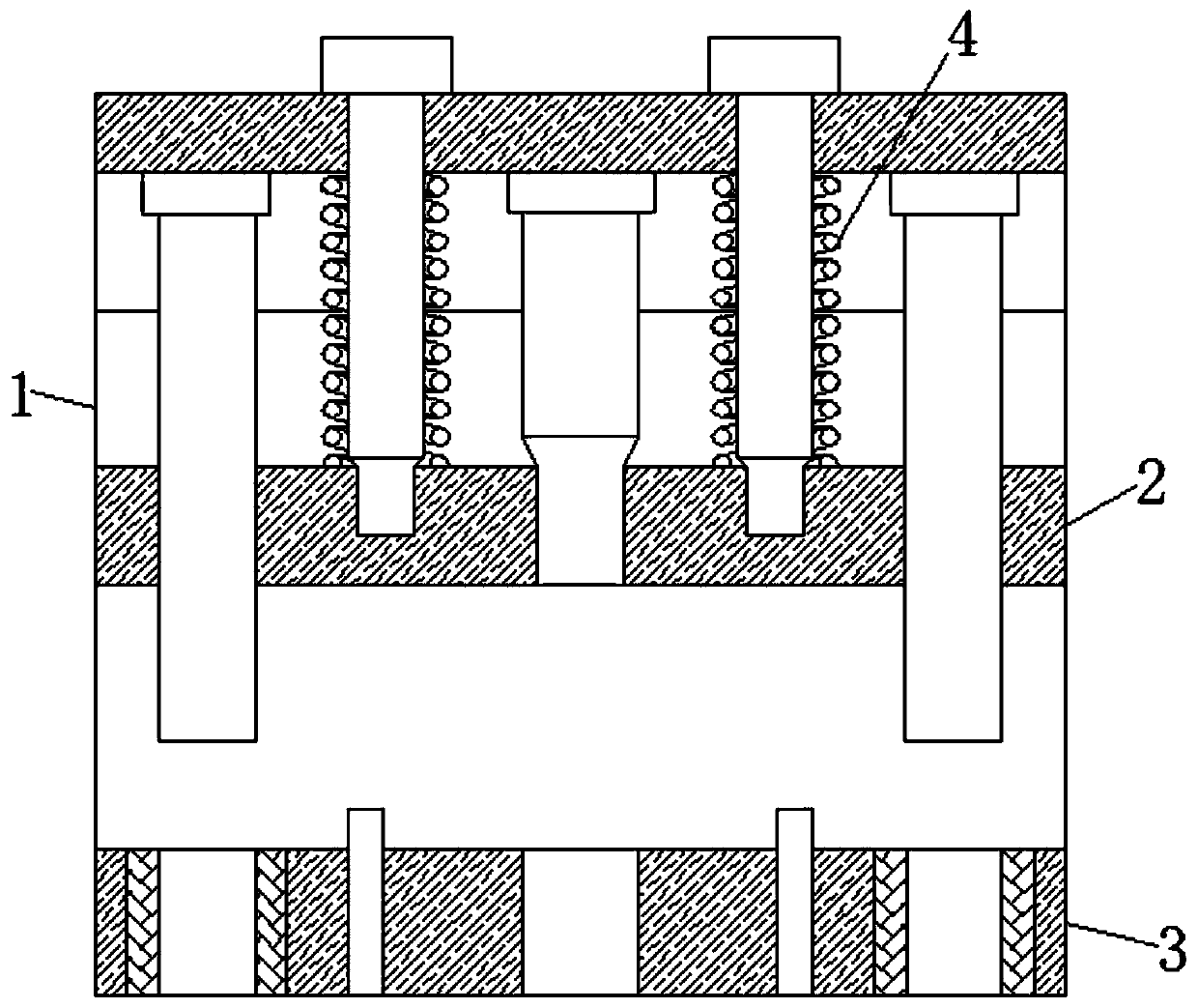
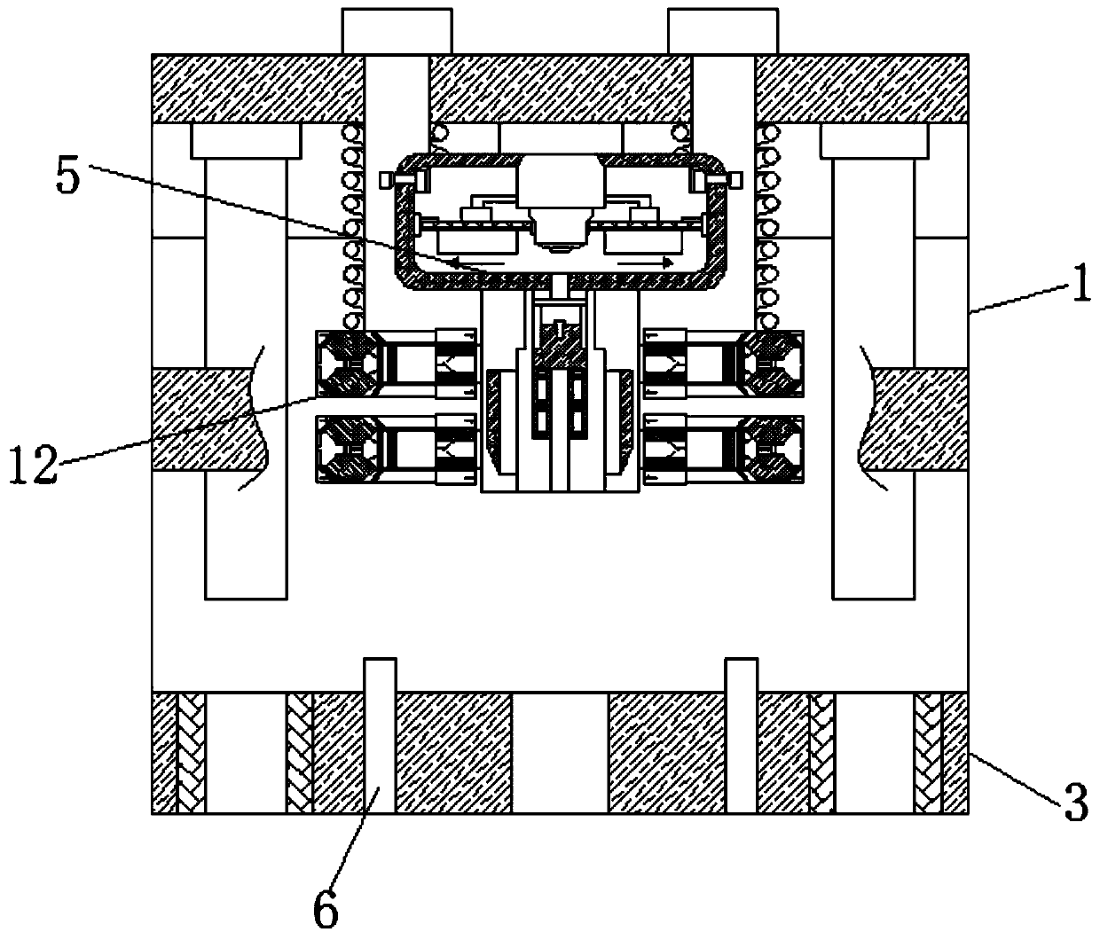
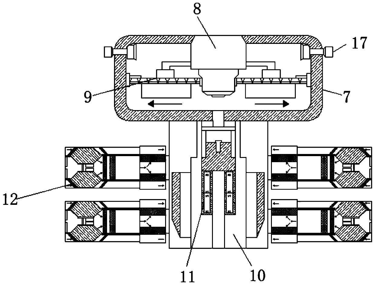
[0021] see Figure 1-4 , a thermoplastic molding device based on the principle of electroluminescence, comprising a support frame 1, an extruded plate 2 is movably connected inside the support frame 1, a bottom plate 3 is movably connected to the lower part of the extruded plate 2, and the upper part of the extruded plate 2 is The spring 4 is movably connected with the inner top wall of the support frame 1, and the inside of the extrusion plate 2 is fixedly co...


PUM


Abstract

The invention relates to the technical field of plastic molding. The invention further discloses thermoplastic plastic forming equipment based on the electroluminescence principle. The equipment comprises a support frame; an extrusion plate is movably connected to the interior of the support frame; the lower part of the extrusion plate is movably connected with a bottom plate; the upper part of the extrusion plate is movably connected with the inner top wall of the support frame through a spring; an electro-optical mechanism is fixedly connected into the extrusion plate, an injection molding channel is formed in the surface of the bottom plate, the electro-optical mechanism comprises a shell, a light-emitting tube is fixedly connected into the shell, and according to the heat effect of current, a conductor can emit heat when powered on, and the law that electric energy is converted into heat energy by conducting the current is quantitatively explained. Due to the fact that the electrode mechanism is arranged on the surface of the extrusion plate, heat generated by current is directly transmitted to the surface of the extrusion plate, the temperature of the surface of the extrusionplate is increased, the temperature difference between the extrusion plate and molten materials is reduced, and the effect that no solid shell appears on the outer layer when the molten materials makecontact with the surface of the cavity is achieved.

Description

technical field [0001] The invention relates to the technical field of plastic molding, in particular to a thermoplastic molding equipment based on the principle of electroluminescence. Background technique [0002] Plastic is a high molecular compound polymerized by addition polymerization or polycondensation reaction with monomer as raw material. It has medium resistance to deformation and is between fiber and rubber. Agents, colorants and other additives. [0003] Among them, plastic molding is an essential step in the production of plastic materials. According to the characteristics of plastic parts, when the molten material contacts the outer layer of the cavity surface, it cools immediately to form a low-density solid shell, and due to the poor thermal conductivity of plastic, the plastic The inner layer of the part is cooled slowly to form a high-density solid layer with large shrinkage, resulting in wall thickness, slow cooling, and high-density layer thickness, whi...

Claims


Application Information

Patent Timeline
Patent Type & Authority Applications(China)
IPC IPC(8): B29C45/00
CPCB29C45/0025
Inventor 李达峰常玉光金慧春
Owner 江苏具鑫包装科技有限公司
Why Eureka
Try Eureka