Photocuring 3D printing device and printing method thereof

A 3D printing and light curing technology, applied in the field of 3D printing, can solve the problems of limited model printing speed, large separation force, and deformation of the solidified model, so as to avoid deformation of the fixed model, reduce separation force, and reduce the bonding area Effect

Active Publication Date: 2022-03-08
YUANZHI TECH SHANGHAI CO LTD
View PDF22 Cites 0 Cited by
  • Summary
  • Abstract
  • Description
  • Claims
  • Application Information

AI Technical Summary

Problems solved by technology

In existing light-curing printing, photosensitive printing material (photosensitive resin) flows in from the side of the cured model, and the path of light-sensitive printing material flowing into the model with a large printing area or with an internal structure is long when printing, and the photosensitive printing material flows into the curing area The speed is slow, affecting the printing speed and accuracy
Moreover, for DLP, LCD or LED printers, the separation force of the cured model bonded to the light-transmitting plate is relatively large, which affects the separation speed and may cause deformation of the cured model
If a curing inhibitor such as oxygen is used to form a curing dead zone above the light-transmitting plate to speed up the inflow of printing materials, but because the thickness of the dead zone is very thin, the printing speed improvement for larger-area models is still limited, and due to the inhibitor The introduction and control of the printing system make the printing system complicated, the cost increases, and the maintenance is inconvenient

Method used


Image

  • Photocuring 3D printing device and printing method thereof
  • Photocuring 3D printing device and printing method thereof
  • Photocuring 3D printing device and printing method thereof

Examples


Embodiment 1

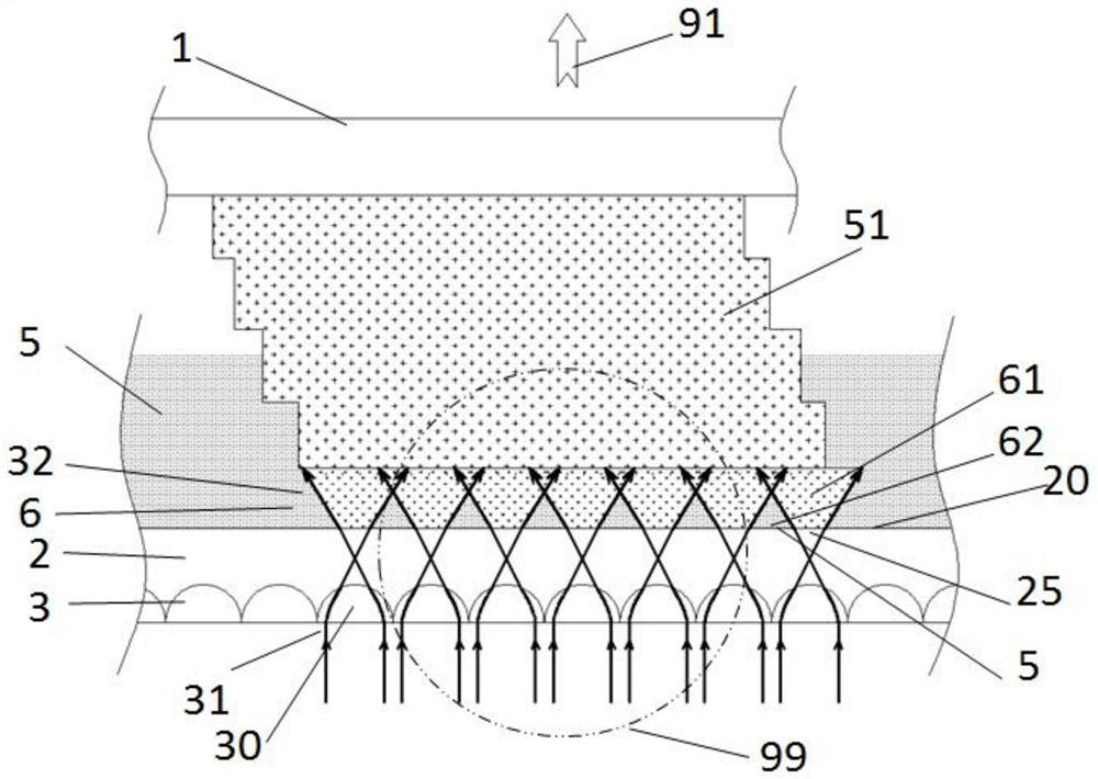
[0083] Such as figure 2As shown, it is illustrated that an optical system 3 (optical system) is formed on the light-transmissive plate 2, and the optical system 3 forms a number of microlens units 30 for the light-transmissive plate 2, and the microlens units 30 are arranged in an array to form a microlens array, The light beams 31 are transformed by the microlens array and emitted from the molding surface 20 of the transparent plate 2 at intervals and diffused to form several beam groups 32 .

[0084] In this embodiment, the optical set 3 adopts a variable refractive index microlens array, that is, several tiny variable refractive index microlens unit arrays are arranged, and the light beam 31 passes through the focus transformation of the variable refractive index microlens array from the light transmission plate 2. Several light beam families 32 are formed by the spaced and expanded emission of the forming surface. The focusing point of the light beam 31 shown in the figu...

Embodiment 2

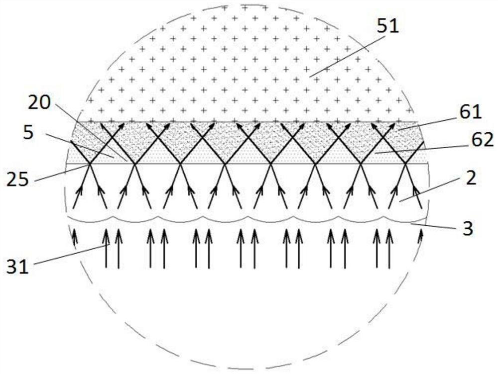
[0086] Such as image 3 It shows that the optical train 3 is formed on the surface of the light-transmitting plate 2, and its schematic position is the same as figure 2 Corresponds to the identification area 99 in. For example, a semi-convex lens array can be provided on the other side of the light-transmitting plate 2 opposite to the molding surface 20 , and the light beams 31 are focused by the semi-convex lens array and emitted from the molding surface 20 of the light-transmitting plate 2 at intervals and diffused to form an arrayed beam group 32 .

[0087] The figure also shows that by setting the focal point of the optical train 3 (that is, the focal point of the light beam 31) on the molding surface 20 of the light-transmissive plate 2, the light-transmitting area 25 can be shrunk into a very small area, even a single Points, the light beam 31 is emitted from the light-transmitting plate 2 and expands to form several beam groups 32 , and irradiates the printing materia...

Embodiment 3

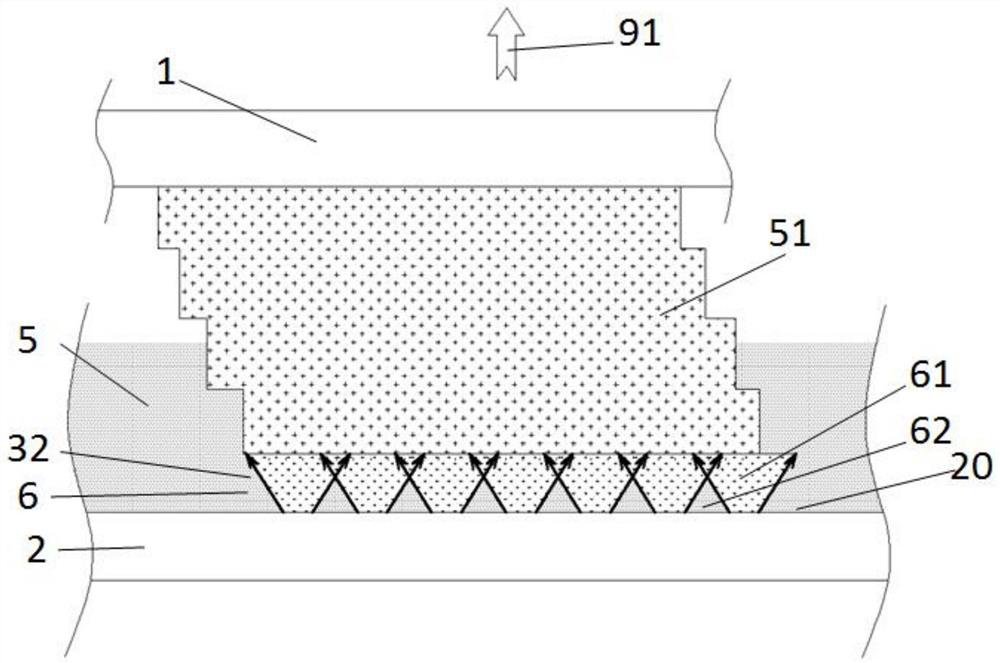
[0090] Such as Figure 4 As shown, it is illustrated that the optical train 3 may be a discrete component independent of the light-transmitting plate 2, and the two are assembled together to realize beam conversion. The optical system 3 is arranged on the irradiation path of the light beam 31. It is shown in the figure that the optical system 3 is formed with microlens units arranged in an array. For example, the planar array of tiny convex lenses is used as an example in the figure. After transformation, the light beams 32 are separated and diffused from the molding surface 20 of the light-transmitting plate 2 to form an arrayed beam group 32 . The microlens array formed by the optical train 3 may be a variable refractive index planar microlens array, or a microconvex lens array, or a microconcave lens array. The optical train 3 can also be different light beam adjustment devices or combinations such as refracting mirrors, reflecting mirrors, diffractive mirrors or gratings....


PUM


Abstract

The invention relates to a light-curing 3D printing device and a printing method thereof. The printing device includes a model plate and a light-transmitting plate, and the model plate and the light-transmitting plate can move relatively. The molding surface of the light-transmitting plate is spaced, diffused and emitted, and several beam families are formed between the molding surface of the light-transmitting plate and the curing model or model plate, and the adjacent beam families partially overlap. The printing method includes the following steps: analyzing the data of the model to be printed; adjusting the relative positions of the model plate and the transparent plate for layer printing; the beams are selectively spaced and diffused from the forming surface of the transparent plate to form a group of beams at intervals, and the beams The printing material in the family area is cured; print layer by layer until the entire model is printed. The invention can increase the speed at which printing material flows between the solidified model and the light-transmitting plate during the printing process, reduce the separation force between the solidified model and the light-transmitting plate, improve printing efficiency, and ensure printing accuracy.

Description

technical field [0001] The invention belongs to the technical field of 3D printing, and in particular relates to a photocuring 3D printing device and a printing method thereof. Background technique [0002] 3D printing is a method of constructing objects by printing layer by layer based on digital model files, including SLA, DLP, LCD / LED and other light curing methods. For example, UV (ultraviolet light) or visible light is used to selectively cure the photocurable resin layer by layer to form a three-dimensional model. For example, the 3D printing method based on DLP (Digital Light Processing) is to project the surface imaging beam formed according to the section pattern of the three-dimensional model onto the photosensitive resin printing material to realize the curing of a single layer, so that the layers are cured and stacked to form a three-dimensional model; SLA (Stereo Lithography Apparatus) is to use the laser beam to focus on the photosensitive resin material throu...

Claims


Application Information

Patent Timeline
Patent Type & Authority Patents(China)
IPC IPC(8): B29C64/129B29C64/264B33Y30/00B33Y10/00
CPCB29C64/129B29C64/264B33Y30/00B33Y10/00
Inventor 季鹏凯
Owner YUANZHI TECH SHANGHAI CO LTD
Why Eureka
Try Eureka