Kitchen waste pretreatment device

A technology for kitchen waste and pretreatment, applied in the fields of waste drying, grain treatment, lighting and heating equipment, etc., can solve the problems of inconvenient transportation and processing, and achieve convenient subsequent processing and transportation, fast and uniform drying, and improved efficiency. Effect

Inactive Publication Date: 2019-12-03
唐红艳
View PDF8 Cites 13 Cited by
  • Summary
  • Abstract
  • Description
  • Claims
  • Application Information

AI Technical Summary

Problems solved by technology

[0002] Kitchen waste is a common domestic waste, which includes various food residues such as vegetable leaves, bones, and waste oil. Due to the mixture of solid waste and liquid waste, it is inconvenient to transport and process. Therefore, this application provides a kind of food waste The pretreatment device realizes the pretreatment of food waste, which is convenient for subsequent transportation and processing

Method used


Image

  • Kitchen waste pretreatment device
  • Kitchen waste pretreatment device
  • Kitchen waste pretreatment device

Examples


Embodiment 1

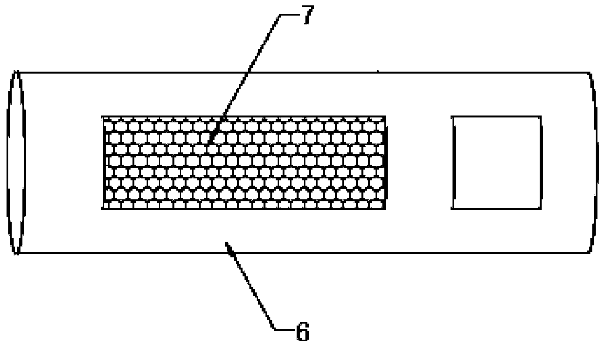
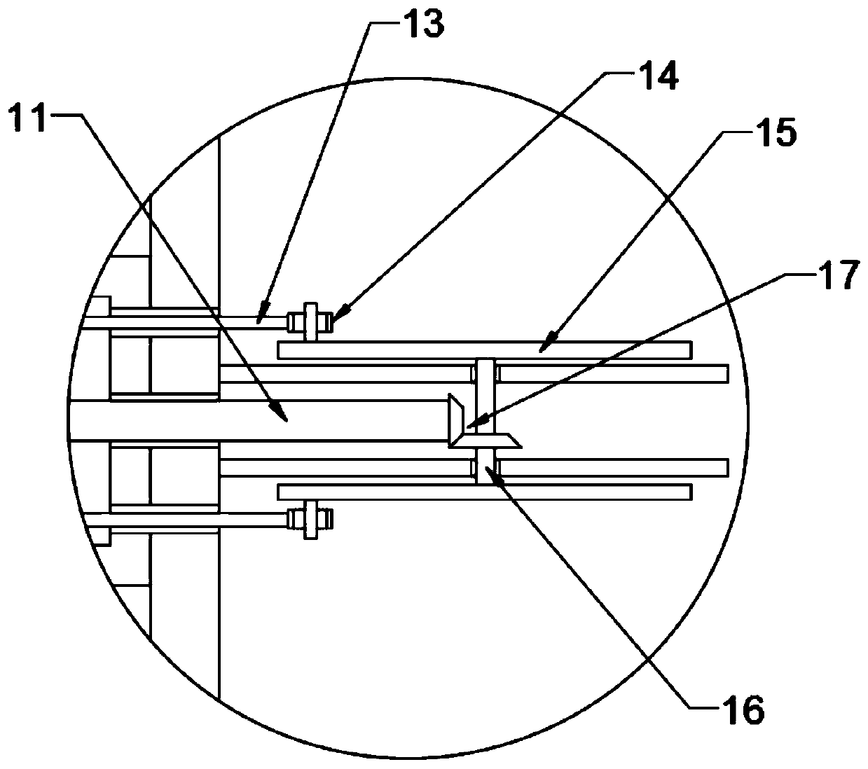
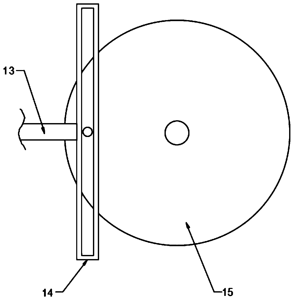
[0021] see Figure 1-4 , in the embodiment of the present invention, a food waste pretreatment device includes a housing 1; the housing 1 is provided with a dehydration cylinder 6, the dehydration cylinder 6 is a cylinder arranged horizontally, and the lower part of the dehydration cylinder 6 is nested with The water leakage net 7 is provided with a water collection cover 8 on the outside of the water leakage net 7, and the water collection cover 8 is fixedly connected with the dewatering cylinder 6, and the water collection cover 8 is connected with a drain pipe 9; the dewatering cylinder 6 is provided with a spiral blade roller 10, The spiral blade roller 10 extends to the outside of the housing 1 and is connected to a drive motor 5 through a coupling, and the drive motor 5 drives the spiral blade roller 10 to rotate, thereby pushing the food waste to move to the right; the right side of the dehydration cylinder 6 is connected to a A feeding pipe 18 ; an extruding plate 12 i...

Embodiment 2

[0025] The difference between this embodiment and Embodiment 1 is that: the feeding pipe 18 is connected with a drying cylinder 19, and the drying cylinder 19 is provided with a rotating shaft 20, and a screw blade 21 is fixedly connected to the rotating shaft 20, and the rotating shaft 20 extends to the housing The output shaft of the drive motor 5 is connected to the outer side of 1 through the second belt, and then the dehydrated kitchen waste is pushed to move; the rotating shaft 20 is a hollow shaft, and air spray heads 23 are evenly distributed on the rotating shaft 20, and the rotating shaft 20 extends to the casing 1. The right side is connected to the air outlet pipe of the hot air blower 29 through the rotary joint 28. The hot air generated by the hot air blower 29 is passed into the rotating shaft 16 and discharged from the air nozzle 23, so as to realize the drying of the kitchen waste in the drying cylinder 19. ; The upper end of the drying cylinder 19 is connected...


PUM


Abstract

The invention discloses a kitchen waste pretreatment device. The kitchen waste pretreatment device comprises a shell, a dehydration barrel is arranged in the shell, and a water leakage net is embeddedat the lower portion of the dehydration barrel. A spiral blade roller is arranged in the dehydration barrel, an extrusion plate is arranged at the right side of the spiral blade roller and is connected with a reciprocating mechanism, the right side of the dehydration barrel communicates with a discharging pipe, and the discharging pipe communicates with a drying cylinder. Through the arrangementof the dehydration barrel, the water leakage net, the water collection cover and the extrusion plate connected with the reciprocating mechanism, the extrusion and dehydration of the kitchen waste is achieved, and the dehydration efficiency is improved. By arranging a hollow rotating shaft provided with the air spraying heads, the kitchen waste is rapidly and evenly dried, and the drying efficiencyis improved. By arranging the extrusion holes and the crushing cutters, the kitchen waste is further crushed, and the follow-up processing and transportation are facilitated.

Description

technical field [0001] The invention relates to the field of domestic waste treatment equipment, in particular to kitchen waste pretreatment equipment. Background technique [0002] Kitchen waste is a common domestic waste, which includes various food residues such as vegetable leaves, bones, and waste oil. Due to the mixture of solid waste and liquid waste, it is inconvenient to transport and process. Therefore, this application provides a kind of food waste The pretreatment device realizes the pretreatment of food waste, which is convenient for subsequent transportation and processing. Contents of the invention [0003] The purpose of the present invention is to provide a kitchen waste pretreatment device to solve the problems raised in the above background technology. [0004] To achieve the above object, the present invention provides the following technical solutions: [0005] A kind of food waste pretreatment equipment, comprising a shell; the shell is provided wit...

Claims


Application Information

Patent Timeline
Patent Type & Authority Applications(China)
IPC IPC(8): B30B9/06B30B15/00B02C18/14B02C4/00F26B17/20F26B21/00F26B5/14
CPCB02C4/00B02C18/0092B02C18/14B02C2201/06B30B9/06B30B15/00F26B5/14F26B17/20F26B21/004F26B2200/04
Inventor 不公告发明人
Owner 唐红艳
Why Eureka
Try Eureka