Geotextile tube bag dehydration device for plain river sediment and dehydration method thereof

A technology of river bottom mud and geotechnical pipe bags, which is applied in chemical instruments and methods, water/sludge/sewage treatment, sludge treatment, etc., and can solve problems such as easy leakage, slow dehydration and solidification speed, and high mud treatment costs , to achieve the effect of improving the overall strength and stability, shortening the curing time, and improving drainage efficiency

Pending Publication Date: 2021-04-09
ZHEJIANG UNIV OF WATER RESOURCES & ELECTRIC POWER
View PDF5 Cites 0 Cited by
  • Summary
  • Abstract
  • Description
  • Claims
  • Application Information

AI Technical Summary

Problems solved by technology

[0003] At present, the mud treatment methods mainly include the sedimentation and air-drying method in the mud pool, the method of transporting the tank car to the designated place, and the mechanical pressing method. These methods have high mud treatment costs, low efficiency, easy leakage, and pollute the city environment. Potential safety hazards or land management and restoration issues in the later stage
The use of flocculant and geotechnical tube bag dewatering is the development direction of rapid dehydration and solidification of sludge and bottom mud, but in the process of actually using geotechnical tube bag, the dehydration effect of geotechnical tube bag is getting worse and worse, making the inside of geotechnical tube bag There is a certain amount of fluid mud with high water content
Due to the flaws in the design of the geotechnical tube bag, it can only be dehydrated by standing still or manually beating for dehydration. The dehydration and curing speed is slow, and it is easy to cause damage to the bag body.

Method used


Image

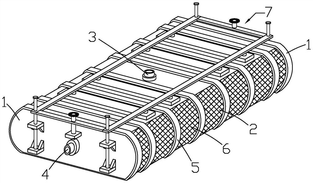
  • Geotextile tube bag dehydration device for plain river sediment and dehydration method thereof
  • Geotextile tube bag dehydration device for plain river sediment and dehydration method thereof
  • Geotextile tube bag dehydration device for plain river sediment and dehydration method thereof

Examples


Embodiment Construction

[0046] It should be noted that, in the case of no conflict, the embodiments in the present application and the features in the embodiments can be combined with each other. The present invention will be described in detail below with reference to the accompanying drawings and examples.

[0047] In order to enable those skilled in the art to better understand the solutions of the present invention, the following will clearly and completely describe the technical solutions in the embodiments of the present invention in conjunction with the drawings in the embodiments of the present invention. Obviously, the described embodiments are only It is an embodiment of a part of the present invention, but not all embodiments. Based on the embodiments of the present invention, all other embodiments obtained by persons of ordinary skill in the art without making creative efforts shall fall within the protection scope of the present invention.

[0048] It should be noted that the terms "fir...


PUM


Abstract

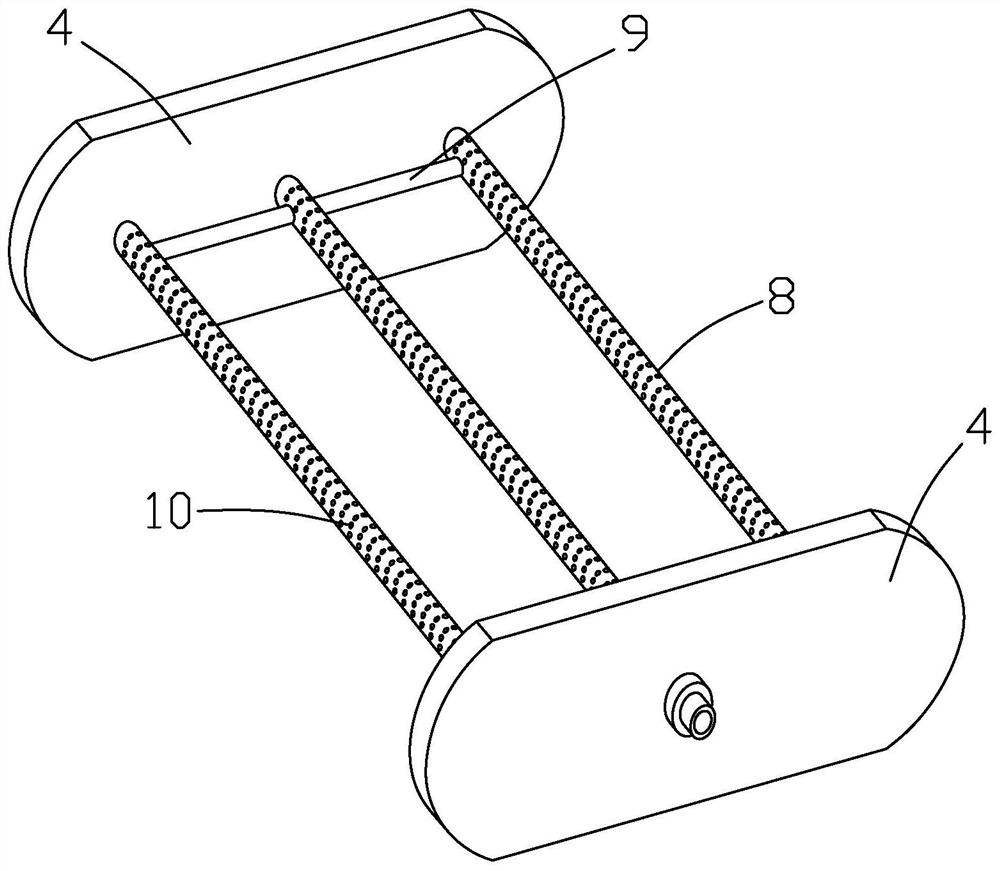
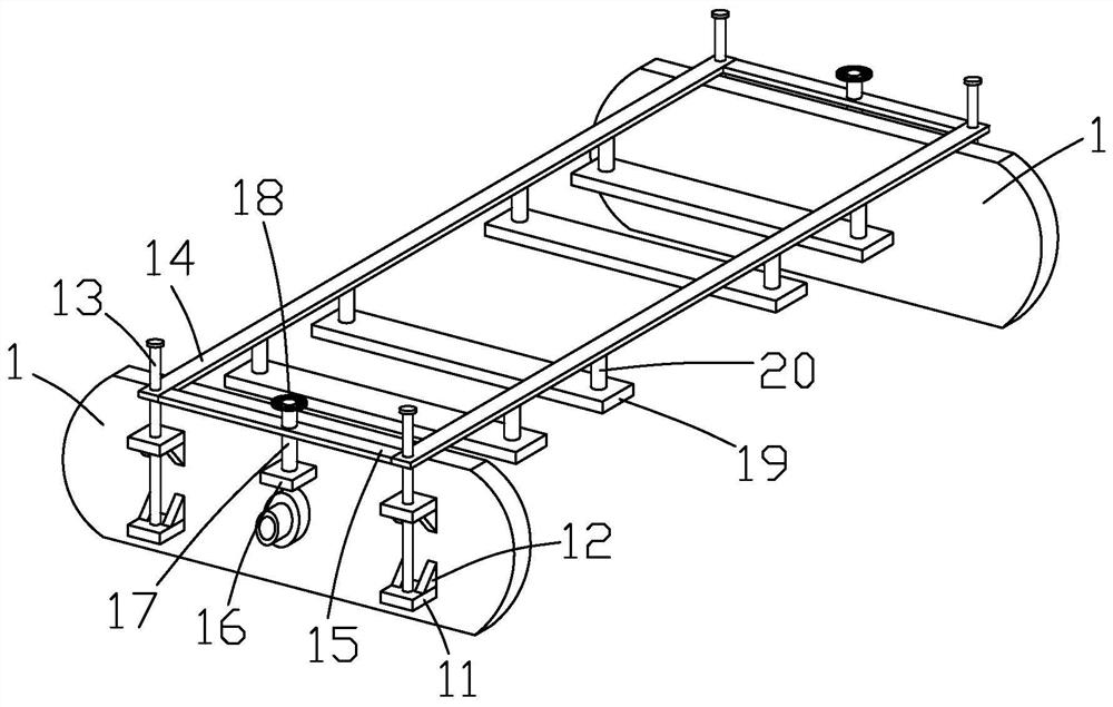
The invention discloses a geotextile tube bag dehydration device for plain river sediment and a dehydration method thereof.The geotextile tube bag dehydration device comprises end cover plates, a bag body, a drainage mechanism and an extrusion mechanism, the drainage mechanism and the bag body are arranged between the two end cover plates, the drainage mechanism is located in the bag body, and a sediment input connector is formed in the top face of the bag body; the extrusion mechanism is connected with the end cover plates on the two sides. The method comprises the steps of end cover plate machining, drainage mechanism machining and mounting, bag body machining and mounting, extrusion mechanism machining and mounting and bottom mud dewatering. The bag body dehydration method is higher in dehydration efficiency, the solidification speed is increased, the bag body can be evenly stressed, bag body damage caused by manual beating is avoided, the dehydration method is simple in step, the labor intensity of manual operation is reduced, the effect of protecting the bag body can be achieved, the service life of the bag body is prolonged, and the dehydration efficiency is improved; The curing time is shortened.

Description

technical field [0001] The invention relates to a geotechnical pipe bag dewatering device for plain river bottom mud and a dewatering method thereof. Background technique [0002] In recent years, my country's infrastructure construction and environmental governance projects have developed rapidly. A large amount of river bottom mud or silt will be produced in river dredging, river dredging, pile foundation hole excavation and other projects. These bottom mud and silt contain a certain amount of suspended liquid of fine soil particles, which have a certain viscosity and need to be left standing for a long time before they can be deposited in layers. [0003] At present, the mud treatment methods mainly include the sedimentation and air-drying method in the mud pool, the method of transporting the tank car to the designated place, and the mechanical pressing method. These methods have high mud treatment costs, low efficiency, easy leakage, and pollute the city environment. ...

Claims


Application Information

Patent Timeline
Patent Type & Authority Applications(China)
IPC IPC(8): C02F11/00C02F11/121
CPCC02F11/008C02F11/121C02F2103/007
Inventor 胡群革殷晖刘学应陈芃
Owner ZHEJIANG UNIV OF WATER RESOURCES & ELECTRIC POWER
Why Eureka
Try Eureka