
High-temperature resistant carbon fiber transition plate for high-speed rail and composite process of high-temperature resistant carbon fiber transition plate

A technology of carbon fiber and high temperature resistance, which is applied in the field of high temperature resistant carbon fiber transition plate for high-speed rail and its composite technology. Achieve the effects of improving safety, reducing energy consumption, and reducing vehicle body weight

Inactive Publication Date: 2019-12-03
ANHUI MEIXIANG IND
View PDF0 Cites 0 Cited by
  • Summary
  • Abstract
  • Description
  • Claims
  • Application Information

AI Technical Summary

Problems solved by technology

[0004] The supporting facilities between the inner windshield of the high-speed rail and the connecting piece between the high-speed train now use an aluminum transition plate. This type of transition plate not only increases the overall weight of the high-speed rail, but also improves the energy consumption of the high-speed rail. Burning effect needs to be improved

Method used


Image

  • High-temperature resistant carbon fiber transition plate for high-speed rail and composite process of high-temperature resistant carbon fiber transition plate
  • High-temperature resistant carbon fiber transition plate for high-speed rail and composite process of high-temperature resistant carbon fiber transition plate
  • High-temperature resistant carbon fiber transition plate for high-speed rail and composite process of high-temperature resistant carbon fiber transition plate

Examples


Embodiment Construction

[0029] The following will clearly and completely describe the technical solutions in the embodiments of the present invention with reference to the accompanying drawings in the embodiments of the present invention. Obviously, the described embodiments are only some, not all, embodiments of the present invention. Based on the embodiments of the present invention, all other embodiments obtained by persons of ordinary skill in the art without making creative efforts belong to the protection scope of the present invention.

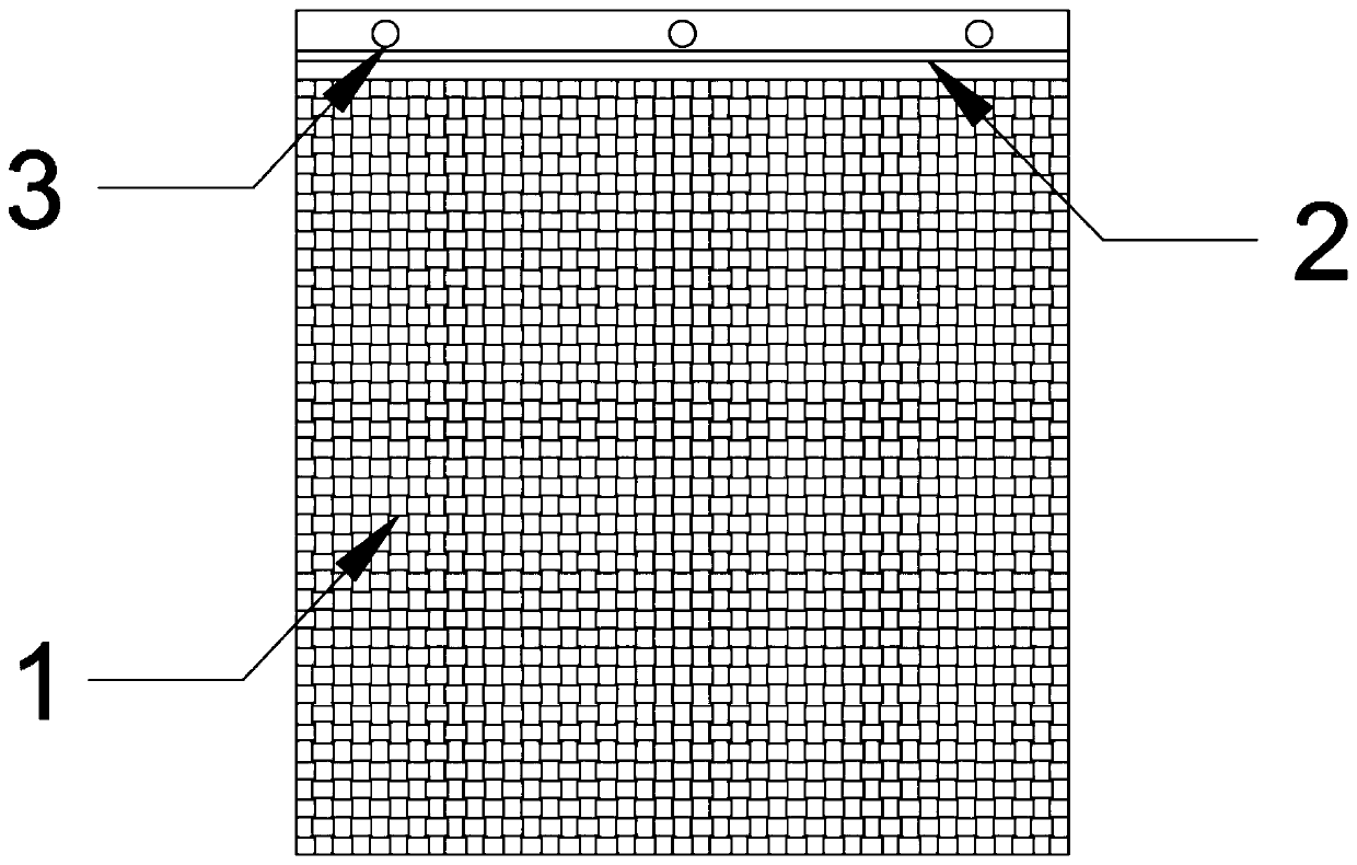
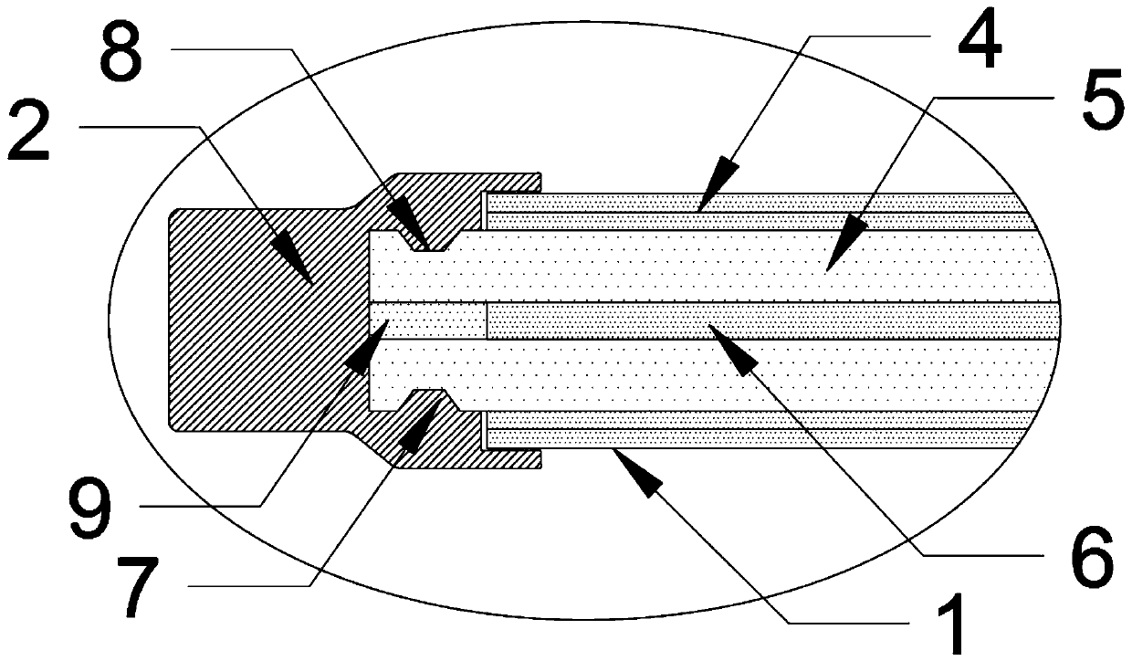
[0030] see Figure 1-3 , the present invention provides a technical solution: a high-temperature-resistant carbon fiber transition plate for high-speed rail and its composite process, including a transition plate body 1, a metal sealing frame 2 and a mounting hole 3, and the end of the transition plate body 1 is fixedly clamped with The metal sealing frame 2, and the surface of the metal sealing frame 2 is equidistantly provided with installation holes 3, the ...


PUM


Abstract

The invention discloses a high-temperature resistant carbon fiber transition plate for high-speed rail and a composite process of the high-temperature resistant carbon fiber transition plate. The high-temperature resistant carbon fiber transition plate comprises a transition plate body, a metal sealing frame and installation holes, the end part of the transition plate body is fixedly clamped withthe metal sealing frame, the installation holes are formed in the surface of the metal sealing frame at equal intervals, the transition plate body comprises carbon fiber surface layers, metal plates and an insulating layer, the metal plates are in two layers arranged parallelly, the insulating layer is pasted between the metal plates, the outer surfaces of the metal plates are pasted with the carbon fiber surface layers, the tensile strength, axial strength and modulus of the carbon fiber transition plate are all greatly improved, the safety of a vehicle body is improved, the density is low, the coefficient of thermal expansion is small, the weight is low, the weight of the vehicle body can be greatly reduced, the energy consumption of vehicle body operation is reduced, the carbon fiber surface layer is matched with the insulating layer of a middle interlayer, the fire protection effect of a device is greatly improved, and thus the flame retardancy, smoke density, melting and droppingproperties, smoke toxicity and the like of the device are greatly improved.

Description

technical field [0001] The invention relates to the technical field of carbon fiber materials, in particular to a high-temperature-resistant carbon fiber transition plate for high-speed rail and a composite process thereof. Background technique [0002] From Japan's Shinkansen in the 1980s to China's new high-speed rail technology developed as a manufacturing brand in recent years, the application of carbon fiber composite materials in high-speed rail manufacturing has been slow. Even in developed Western Europe, carbon fiber composites are used in high-speed rail. The proportion of the material is also not more than 20%. This is because, in the process of material selection and application, it is necessary to fully consider that high-speed trains have high strength requirements, high fatigue resistance, collision resistance, impact resistance, wind and sand wear resistance, temperature difference and humidity change resistance, good vibration and sound insulation effects, a...

Claims


Application Information

Patent Timeline
IPC IPC(8): B32B15/14B32B15/20B32B9/00B32B9/04B32B3/08B32B3/06B32B33/00B32B37/02B32B37/10B32B37/00B32B37/06B61D17/04
CPCB32B3/06B32B3/08B32B5/02B32B5/26B32B15/14B32B15/20B32B33/00B32B37/003B32B37/02B32B37/06B32B37/10B32B2250/40B32B2260/023B32B2260/046B32B2262/106B32B2307/306B32B2307/54B32B2605/10B61D17/04
Inventor 汪华北陈金琪李志杰
Owner ANHUI MEIXIANG IND
Learn More