
Laser cladding device and method for repairing rolling mill housing

A technology of laser cladding and rolling mill arch, which is applied in the direction of metal material coating process, coating, etc., can solve the problems of rolling mill arch size deformation, lack of strengthening effect, and high labor intensity of workers, so as to achieve small heat-affected zone, Small thermal deformation and reduced work intensity

Pending Publication Date: 2019-12-03
武汉武钢华工激光大型装备有限公司
View PDF4 Cites 2 Cited by
  • Summary
  • Abstract
  • Description
  • Claims
  • Application Information

AI Technical Summary

Problems solved by technology

[0008] Disadvantages: Since the nature of the surface of the rolling mill archway has not been changed, it has not played a strengthening role, so after a period of use, it needs to be repaired again
[0011] Disadvantages: short service life, frequent replacement, high labor intensity
[0014] Disadvantages: The heat input of surfacing welding is large, which may cause the problem of deformation of the size of the rolling mill archway, and it is prone to welding defects and it is difficult to obtain a uniform and dense surfacing layer

Method used


Image

  • Laser cladding device and method for repairing rolling mill housing
  • Laser cladding device and method for repairing rolling mill housing
  • Laser cladding device and method for repairing rolling mill housing

Examples


Embodiment Construction

[0046]The following will clearly and completely describe the technical solutions in the embodiments of the present invention with reference to the accompanying drawings in the embodiments of the present invention. Obviously, the described embodiments are only a part of the present invention, not all embodiments. Based on the embodiments of the present invention, all other embodiments obtained by persons of ordinary skill in the art without making creative efforts belong to the protection scope of the present invention.

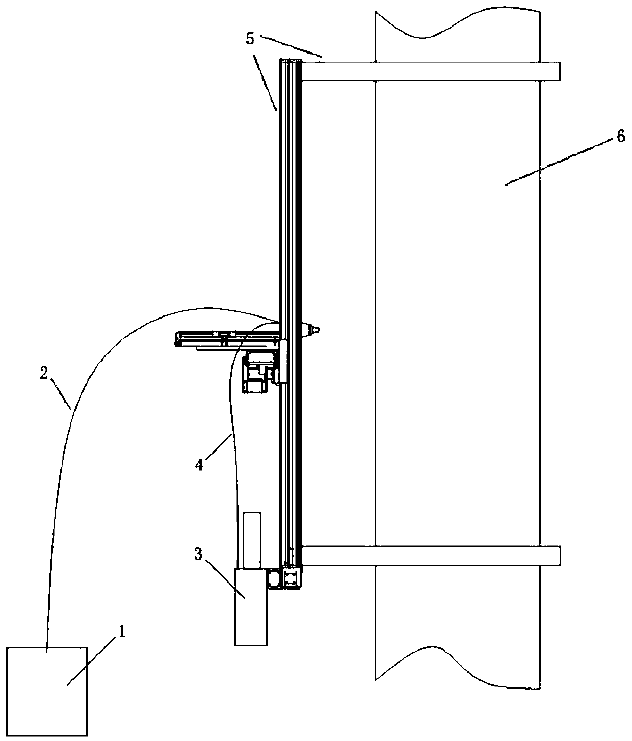
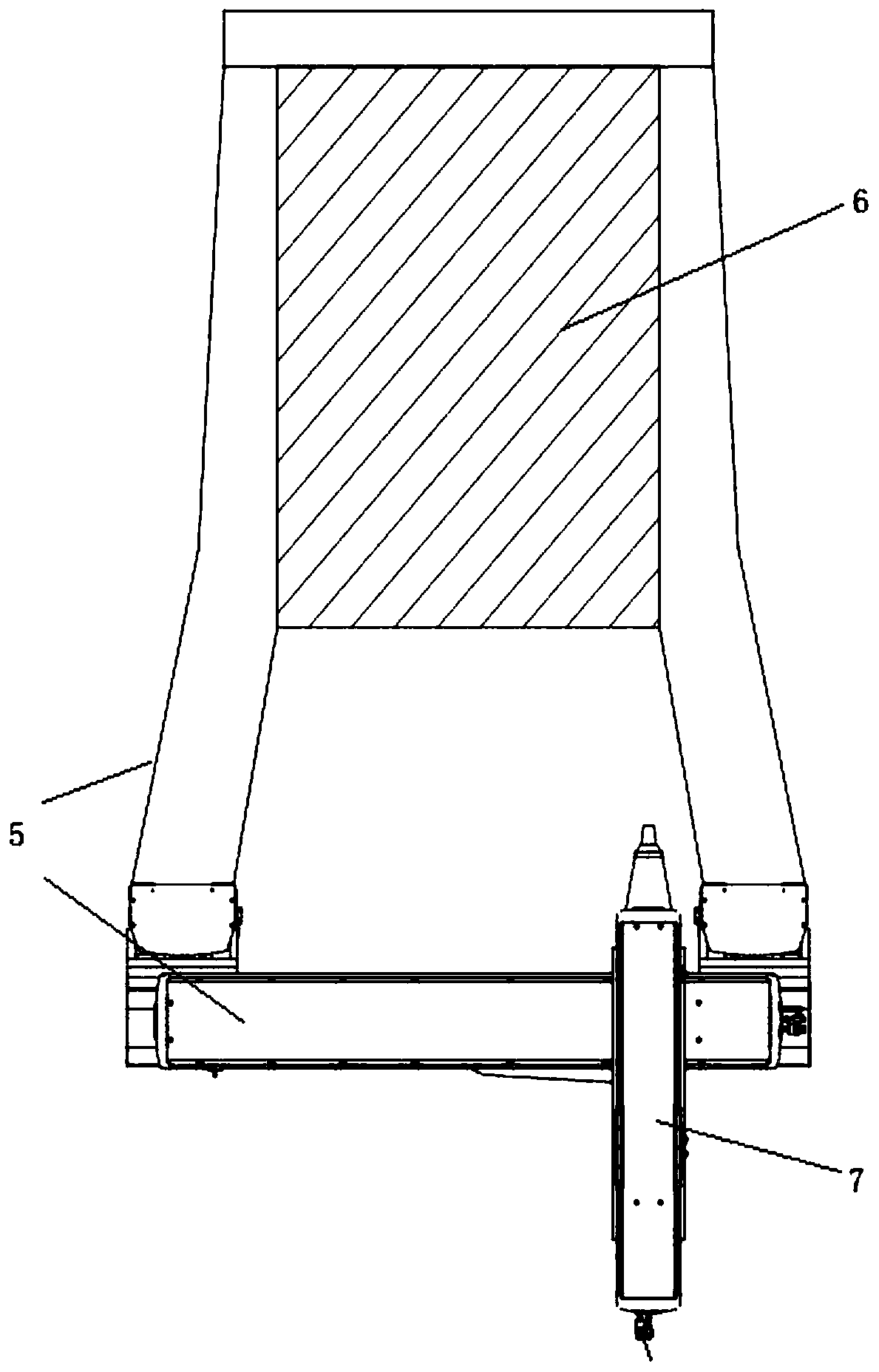
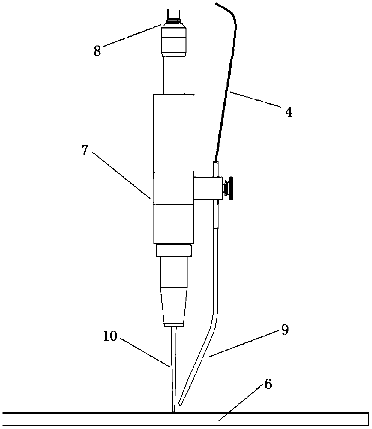
[0047] Such as figure 1 As shown, as the first embodiment of the present invention, a laser cladding device for repairing a rolling mill archway is provided, the device includes a laser cladding unit and a gantry type linear module 5, and the laser cladding unit includes a laser emitter 1. Laser cladding processing head 7 and powder feeder 3, the laser cladding processing head 7 has a laser channel and a powder feeding channel, and has an output optical connec...


PUM

PropertyMeasurementUnit
poweraaaaaaaaaa
wavelengthaaaaaaaaaa

Abstract

The invention discloses a laser cladding device for repairing a rolling mill housing. The device comprises a laser cladding unit and a gantry type linear module, the laser cladding unit comprises a laser emitter, a laser cladding processing head and a powder feeder; the laser emitter is connected with an output optical connector of the laser cladding processing head through a transmission opticalfiber. The laser cladding processing head is used for emitting laser emitted by the laser emitter through the laser cladding processing head. The powder feeder is connected with a powder feeding channel of the laser cladding processing head through a powder feeding pipe and used for conveying cladding powder into a molten pool of a light spot irradiation area to achieve laser cladding processing during laser irradiation. The laser cladding processing head is mounted on the linear module; the linear module is fixed to a to-be-repaired area on the rolling mill housing, the laser cladding machining head is made to right face the to-be-repaired area on the rolling mill housing, and the linear module drives the laser cladding processing head to linearly move in multiple directions relative to the surface of the rolling mill housing so as to adjust the position of the laser cladding processing head relative to the to-be-repaired area of the rolling mill housing.

Description

technical field [0001] The invention relates to the technical field of laser processing, in particular to a laser cladding device and method for repairing a rolling mill archway. Background technique [0002] The rolling mill archway, also known as the rolling mill frame and the frame body, is an overall frame structure, which mainly plays a supporting and fixing role in the rolling mill, and is an important part of the hot rolling, cold rolling, continuous rolling and other rolling mills. The rolling mill archway is the part with the largest size and weight in the working stand of the rolling mill. It is mainly composed of columns and beams with thick cross-sections. The whole set of rolls and roll adjustment devices are installed on it. The stand must bear all the rolling force during rolling. And the huge impact load when biting into the billet, and the stand is a permanent part of the rolling mill, so it has high requirements for its strength. [0003] During the workin...

Claims


Application Information

Patent Timeline
Patent Type & Authority Applications(China)
IPC IPC(8): C23C24/10
CPCC23C24/103
Inventor 柳洁喻云李春旺张炜
Owner 武汉武钢华工激光大型装备有限公司
Learn More