Robot rapid repositioning method and system based on visual dictionary

A visual dictionary and robot technology, applied to radio wave measurement systems, instruments, computer components, etc., can solve the problems of no repositioning, robot inconvenience, etc., and achieve the effect of avoiding manual intervention, simple method, and strong robustness

Pending Publication Date: 2019-12-03
的卢技术有限公司
View PDF3 Cites 44 Cited by
  • Summary
  • Abstract
  • Description
  • Claims
  • Application Information

AI Technical Summary

Problems solved by technology

However, due to the inherent shortcomings of the lidar sensor, when the tracking and positioning failure occurs, it does not have the ability to relocate. Therefore, once the tracking and positioning failure occurs, the robot needs to be reset to the original position, which brings difficulties to the normal use of the robot. great inconvenience

Method used


Image

  • Robot rapid repositioning method and system based on visual dictionary
  • Robot rapid repositioning method and system based on visual dictionary
  • Robot rapid repositioning method and system based on visual dictionary

Examples


Embodiment 1

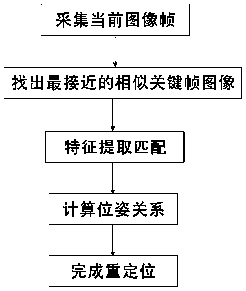
[0028] In the first embodiment of the present invention, a fast relocation method based on a visual dictionary is provided. When the robot fails to locate using the laser radar sensor 200 and loses the location of the robot, the image acquired by the image acquisition module 100 can be used to quickly relocate. Robot relocation. Specifically, refer to figure 1 , including the following steps,

[0029] Step 1: Use the image acquisition module 100 to obtain the current image frame, compare it with the key frames stored in the visual map, and find out the closest similar key frame. In this step, the visual map is established based on the visual SLAM algorithm. The image acquisition module 100 can be a camera or a camera, which can collect a single frame of image information. The image acquisition module 100 is set on the robot and can follow the robot. When the robot fails to locate, The image collection module 100 collects the current image frame, compares the current image fr...

Embodiment 2

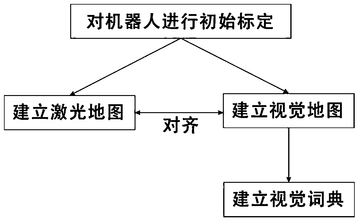
[0057] refer to figure 2 , is the second embodiment of the present invention, and this embodiment is different from the previous embodiment in that it also includes the following steps,

[0058] Step 1: Initially calibrate the robot using the image acquisition module 100 . Specifically, this step includes performing calibration using a checkerboard calibration board and Zhang's calibration method to obtain camera internal parameter coefficients and distortion coefficients. Those in this profession can understand that Zhang’s calibration method is a camera calibration method based on a single-plane checkerboard. This method only requires a printed checkerboard, and the calibration is simple. The camera and calibration board can be placed arbitrarily, and the calibration The precision is high.

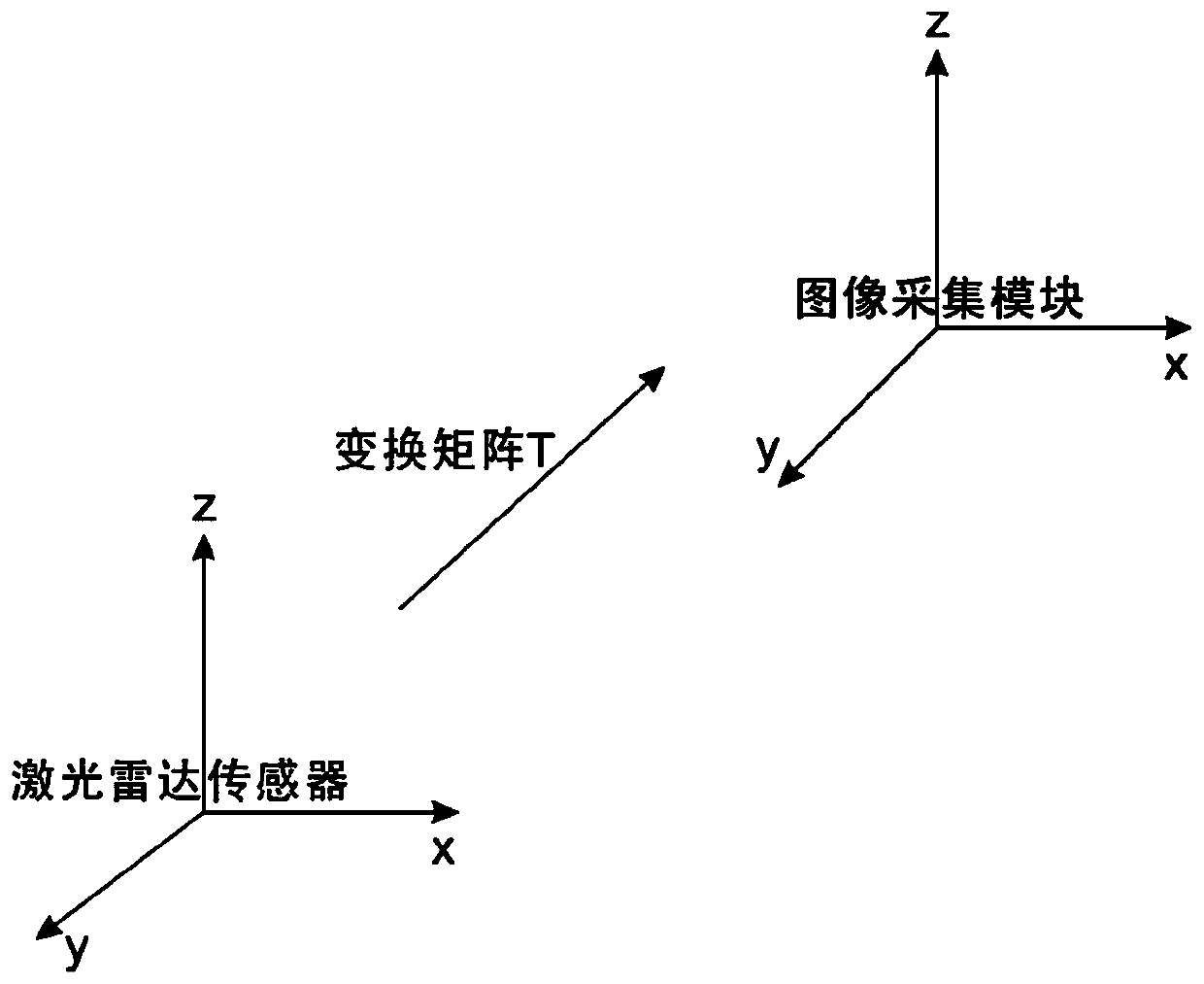
[0059] refer to image 3 , measuring the coordinate system transformation matrix T between the laser radar sensor 200 and the image acquisition module 100, the transformation matrix ...

Embodiment 3

[0093] refer to Figure 4 , which is a visual dictionary-based fast robot relocation system proposed in this embodiment, and the visual dictionary-based fast robot relocation method in the above embodiments can be applied to the robot fast relocation system. Specifically, the system can be divided into a software module and a hardware module, wherein the hardware module includes an image acquisition module 100 and a laser radar sensor 200, the image acquisition module 100 is used to collect image information around the robot, and the laser radar sensor 200 is used to collect the For the distance information between the surrounding objects and the robot, the image acquisition module 100 can use a camera or a camera to purchase image information. The laser radar sensor 200 is a sensor that uses laser technology for measurement, and is composed of a laser, a laser detector and a measurement circuit. Realize non-contact long-distance measurement, fast speed, high precision, large ...


PUM


Abstract

The invention discloses a robot rapid repositioning method and system based on a visual dictionaryThe method comprises the following steps: obtaining a current image frame through an image collectionmodule, comparing the current image frame with a key frame stored in a visual map, and finding out the closest similar key frame; performing feature matching on the current image frame and the similarkey frame to obtain a pose relationship of the pose of the current image frame relative to the similar key frame; and according to the pose of the similar key frame in the laser map and the pose relationship of the current image frame relative to the similar key frame, pose information of the current robot is obtained, and repositioning is completed. The method has the advantages that the imagesare acquired by the image acquisition module, repositioning is performed when the robot fails to perform positioning by the aid of the laser radar sensor, and the method is simple, high in robustnessand free of manual intervention.

Description

technical field [0001] The invention relates to the technical field of intelligent positioning, in particular to a method and system for fast repositioning of a robot based on a visual dictionary. Background technique [0002] The development of SLAM technology has a history of more than 30 years, involving many technical fields. Since it contains many steps, each step can be implemented using different algorithms, SLAM technology is also a popular research direction in the field of robotics and computer vision. The full English name of SLAM is Simultaneous Localization and Mapping, which is called "Simultaneous Localization and Mapping" in Chinese. SLAM tries to solve such a problem: a robot moves in an unknown environment, how to determine its own trajectory through observation of the environment, and at the same time construct a map of the environment. [0003] In the technical field related to robots, precise positioning is a very important part. The current mainstrea...

Claims


Application Information

Patent Timeline
Patent Type & Authority Applications(China)
IPC IPC(8): G06T7/73G06T7/80G06K9/46G06K9/62G01S17/87G01S17/42
CPCG06T7/73G06T7/80G01S17/875G01S17/42G06T2207/30208G06T2207/10004G06T2207/10044G06V10/424G06V10/757G06V10/462
Inventor 赵强
Owner 的卢技术有限公司
Why Eureka
Try Eureka