A wafer transfer manipulator and wafer flipping method thereof

A technology of manipulators and wafers, applied in conveyor objects, transportation and packaging, electrical components, etc., can solve problems such as the impact of transmission efficiency, reduce wafer cleanliness, etc., and achieve the effect of high space utilization and compact travel.

Active Publication Date: 2021-05-25
HANGZHOU ZHONGGUI ELECTRONICS TECH CO LTD
View PDF5 Cites 0 Cited by
  • Summary
  • Abstract
  • Description
  • Claims
  • Application Information

AI Technical Summary

Problems solved by technology

However, this implementation method needs to move the manipulator above the drying equipment as a whole, so that the claw clamping arm can place the wafer that has been turned over by the wafer jaws into the drying equipment. This wafer transfer robot is located above the drying equipment as a whole. During the insertion process, it is easier to introduce impurity particles into the final drying process, reducing the cleanliness of the wafer
Moreover, the lateral stroke of the wafer transfer manipulator runs through the entire cleaning module, and the long-stroke transfer also has a certain impact on the transfer efficiency.

Method used


Image

  • A wafer transfer manipulator and wafer flipping method thereof
  • A wafer transfer manipulator and wafer flipping method thereof
  • A wafer transfer manipulator and wafer flipping method thereof

Examples


Embodiment 1

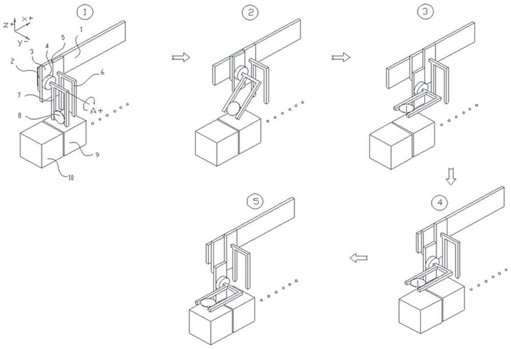
[0049] After the first jaw holding arm 7 moves along the Z-axis direction and takes out the wafer 8 from the pre-drying unit 9 (such as figure 2 as shown in part ①), such as figure 2 As shown in part ②, the horizontal transfer carriage 2 moves in the X+ direction, and at the same time, the rotary table 4 drives the wafer 8 to rotate clockwise along A+, and the first vertical lifting axis 3 carries the first jaw clamping arm 7 in the Z- direction Moving downward, the first jaw clamping arm 7 carries the wafer 8 to move together in the three directions of X+, A+, and Z-, and coordinates to complete the state transition process of the wafer 8 from vertical to horizontal, such as figure 2 As shown in part ③ of , the wafer 8 has reached a horizontal state. During the flipping of the wafer 8 , the designated mechanism inside the drying unit 10 is ready to put the wafer 8 into it. Then the horizontal transfer carriage 2 drives the first claw clamping arm 7 to move to the X-direc...

Embodiment 2

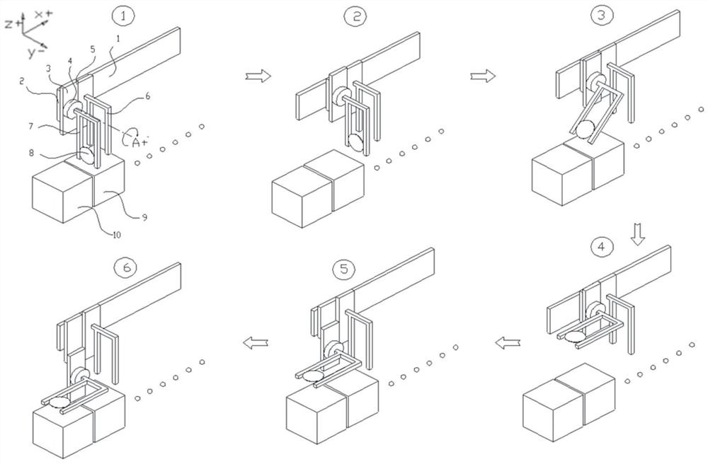
[0051] After the first jaw holding arm 7 moves along the Z-axis direction and takes out the wafer 8 from the pre-drying unit 9 (such as image 3 as shown in part ①), such as image 3 As shown in part ②, the horizontal transfer carriage 2 moves a certain distance in the X+ direction, and then the rotary table 4 drives the first claw clamping arm 7 to rotate clockwise along A+ to a certain angle to make the wafer 8 reach a horizontal state (such as image 3 ③ and ④ part shown). Then the first vertical lifting shaft 3 and the first claw clamping arm 7 move downward to a certain position in the Z-direction. During the flipping of the wafer 8 , the designated mechanism inside the drying unit 10 is ready to put the wafer 8 into it. Then the horizontal transfer carriage 2 drives the first claw clamping arm 7 to move to the X-direction until the wafer 8 is located above the drying unit 10 (such as image 3 shown in part ⑤). The first claw clamping arm 7 moves downward in the Z-dir...

Embodiment 3

[0053] After the first jaw holding arm 7 moves along the Z-axis direction and takes out the wafer 8 from the pre-drying unit 9 (such as Figure 4 as shown in part ①), such as Figure 4 As shown in part ②, the horizontal transfer carriage 2 moves a certain distance in the X+ direction, and then the rotary table 4 drives the first claw clamping arm 7 to rotate clockwise along A+ to a certain angle to make the wafer 8 reach a horizontal state (such as Figure 4 ③ and ④ part shown). Then the horizontal transfer carriage 2 drives the first claw clamping arm 7 to move in the X-direction (as Figure 4 ⑤), and then the first vertical lifting shaft 3 and the first claw clamping arm 7 move down in the Z-direction until the wafer 8 is located in the designated mechanism inside the drying unit 10 (such as Figure 4 shown in part ⑥). Finally, the first clamping arm 7 releases the wafer 8 , and the wafer 8 is located on the designated mechanism inside the drying unit 10 .


PUM


Abstract

The invention discloses a wafer transfer manipulator and a wafer flipping method thereof. The wafer transfer manipulator comprises: a lateral transfer shaft located only on one side of the cleaning unit; a lateral transfer carriage arranged on the lateral transfer shaft and can move horizontally along the horizontal transmission shaft; the first vertical lifting shaft is arranged on the horizontal transmission carriage and can move vertically on the horizontal transmission carriage; the rotary table is arranged on On the first vertical lifting shaft; the clamping arm of the first claw is connected with the rotary table and is driven by the rotary table to rotate. The invention can satisfy the free conversion of the wafer in the horizontal and vertical states; the horizontal transfer carriage will not run directly above the drying unit, thereby eliminating the scattering of impurity particles on the moving parts of the wafer transfer manipulator during the drying process to the wafer possibility.

Description

technical field [0001] The invention relates to the field of equipment for manufacturing semiconductor integrated circuit chips, in particular to a wafer transfer manipulator and a wafer flipping method thereof. Background technique [0002] With the rapid development of the semiconductor industry, the feature size of integrated circuits tends to be miniaturized, and semiconductor chips continue to develop in the direction of small size, high circuit density, fast speed, and low power consumption. Integrated circuits have now entered the ultra-large-scale integrated circuit (Ultra -Large-scale integration, ULSI) sub-micron technology stage. With the gradual increase of the diameter of the silicon wafer, the width of the reticle in the component is gradually reduced, and the number of metal layers is increased. Therefore, the high planarization of the surface of the semiconductor film has an important impact on the high performance, low cost, and high yield of the device. As...

Claims


Application Information

Patent Timeline
Patent Type & Authority Patents(China)
IPC IPC(8): H01L21/687H01L21/677
CPCH01L21/67766H01L21/68721H01L21/67718
Inventor 杨思远沈凌寒臧志城
Owner HANGZHOU ZHONGGUI ELECTRONICS TECH CO LTD
Why Eureka
Try Eureka