Millimeter wave antenna and wireless equipment

A millimeter-wave antenna and wireless device technology, which is applied in the field of antenna device and millimeter-wave antenna structure design, can solve the problems of large layout space of millimeter-wave antennas and is not suitable for small-sized wireless devices, and achieve simplified design and simple structure , small size effect

Active Publication Date: 2019-12-03
GEER TECH CO LTD
View PDF8 Cites 2 Cited by
  • Summary
  • Abstract
  • Description
  • Claims
  • Application Information

AI Technical Summary

Problems solved by technology

Therefore, traditional millimeter-wave antennas need to occupy a large layout space and are not suitable for popularization and application in small-sized wireless devices.

Method used


Image

  • Millimeter wave antenna and wireless equipment
  • Millimeter wave antenna and wireless equipment
  • Millimeter wave antenna and wireless equipment

Examples


Embodiment 1

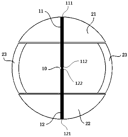
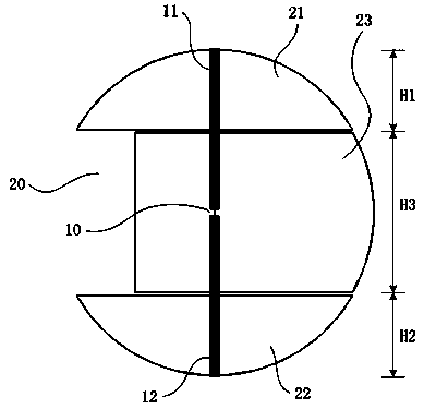
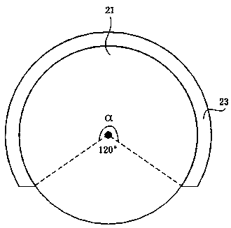
[0031] Embodiment 1, this embodiment proposes a structural design of a millimeter wave antenna, see Figure 1-Figure 4 As shown, the millimeter wave antenna in this embodiment is a spherical antenna structure, including radiators, first conductive pillars 11 and second conductive pillars 12 and other main components. Wherein, the radiator is designed in the shape of a hollow sphere with a gap 20; the first conductive post 11 and the second conductive post 12 are connected to the radiator, and are at least partially located in the spherical cavity formed by the radiator to form a cavity Bulk resonance probes. As a preferred embodiment, in this embodiment, a plurality of radiators 21-23 are combined to form the hollow sphere. Specifically, each of the radiators 21 - 23 may be designed in a curved surface shape, and after these radiators 21 - 23 in the curved surface shape are put together, a hollow sphere with a gap 20 can just be formed. In some embodiments, the radiators 21-...

Embodiment 2

[0042] Embodiment 2. This embodiment proposes a wireless device based on millimeter wave antenna design. Specifically, the millimeter-wave antenna with directional high gain and adjustable radiation angle proposed in Embodiment 1 can be applied to a wireless device and connected to a radio frequency circuit in the wireless device. When connecting, the positive pole of the radio frequency circuit in the wireless device can be electrically connected with the free end 112 of the first conductive post 11 in the millimeter wave antenna, and the negative pole of the radio frequency circuit can be electrically connected with the second conductive post 12 to realize electrical signals and RF signal feed.

[0043] As a preferred connection method between the millimeter wave antenna and the radio frequency circuit, this embodiment proposes a coaxial feeding structure, such as Figure 5 shown. Specifically, the second conductive post 12 can be designed as a hollow conductor, for exampl...


PUM


Abstract

The invention discloses a millimeter wave antenna and wireless equipment. A radiator, a first conductive column and a second conductive column are included. The radiator forms a hollow sphere with a notch. The first conductive column is connected with the radiator, and one end extends into the hollow sphere to form a free end. The second conductive column is connected with the radiator, one end extends into the hollow sphere to form the free end, and the free end of the first conductive column and the free end of the second conductive column directly face each other and form a gap. The millimeter wave antenna is designed to adopt a spherical structure, and miniaturization of a size of the antenna can be achieved. The antenna can generate directional radiation towards a notch direction through a spherical cavity so that the antenna has directional high-gain performance. Through changing the notch direction of the antenna, a radiation angle of the antenna can be adjusted, and traceability of a radiation pattern of the antenna is realized.

Description

technical field [0001] The invention belongs to the technical field of wireless equipment, and relates to an antenna device in a wireless equipment, in particular to a structural design of a millimeter-wave antenna. Background technique [0002] Antenna is an important part of wireless devices used to receive or transmit electromagnetic waves. Wireless devices that transmit and receive wireless signals through antennas for communication can get rid of the shackles of signal cables and realize more abundant applications. In real life, antennas are used more and more widely, and antennas are needed in more and more electronic products. With the upgrading of wireless devices, the design of antennas also faces more challenges. [0003] In the field of wireless communication, the era of millimeter waves has come quietly. Millimeter wave (millimeter wave) is an electromagnetic wave with a wavelength of 1 to 10 millimeters. It is located in the wavelength range where microwaves an...

Claims


Application Information

Patent Timeline
Patent Type & Authority Applications(China)
IPC IPC(8): H01Q1/38H01Q1/50H01Q3/08
CPCH01Q1/38H01Q1/50H01Q3/08
Inventor 徐成峰
Owner GEER TECH CO LTD
Why Eureka
Try Eureka