Two-stage damage location recognition method based on guided-wave signal sparse decomposition and damage localization

A damage location and signal sparse technology, which is applied in the processing of detection response signals, the use of sound waves/ultrasonic waves/infrasonic waves to analyze solids, and the use of sound waves/ultrasonic waves/infrasonic waves for material analysis, etc., can solve the problem of inaccurate ultrasonic guided wave signal analysis results, The dictionary design method and signal sparse decomposition algorithm are not perfect enough to achieve the effect of reducing possibility and good robustness

Active Publication Date: 2019-12-06
哈尔滨工业大学人工智能研究院有限公司
View PDF9 Cites 3 Cited by
  • Summary
  • Abstract
  • Description
  • Claims
  • Application Information

AI Technical Summary

Problems solved by technology

[0004] The present invention aims to solve the problem that the dictionary design method and signal sparse decomposition algorithm existing in sparse representation in the identification of overlapping wave packets of ultrasonic guided wave signals are not perfect enough, which leads to the problem that the results obtained by analyzing ultrasonic guided wave signals are not accurate enough, and now provides a method based on A Two-Stage Damage Location Identification Method Based on Sparse Decomposition of Guided Wave Signals and Damage Location

Method used


Image

  • Two-stage damage location recognition method based on guided-wave signal sparse decomposition and damage localization
  • Two-stage damage location recognition method based on guided-wave signal sparse decomposition and damage localization
  • Two-stage damage location recognition method based on guided-wave signal sparse decomposition and damage localization

Examples


specific Embodiment approach 1

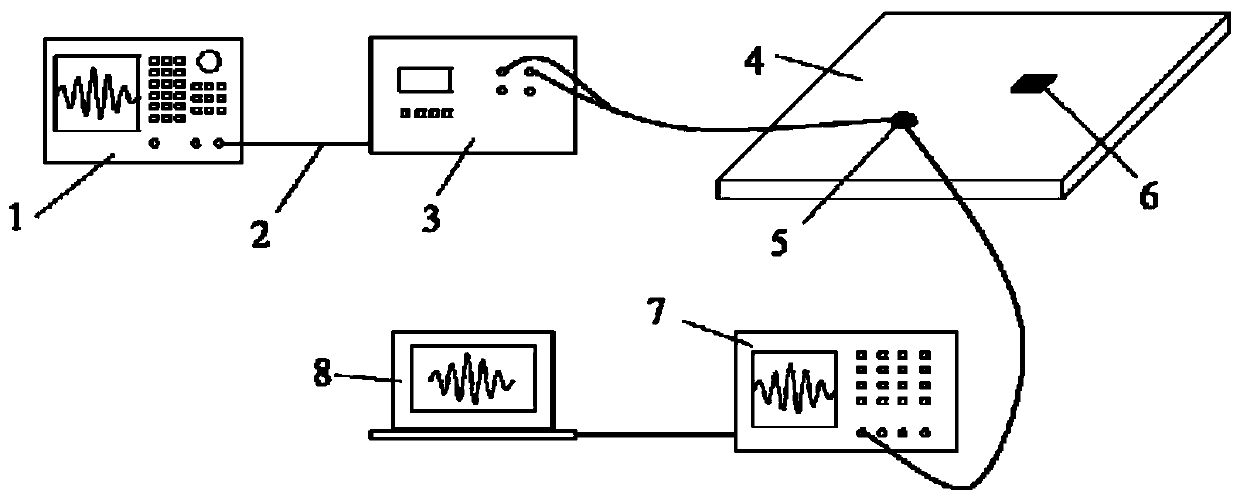
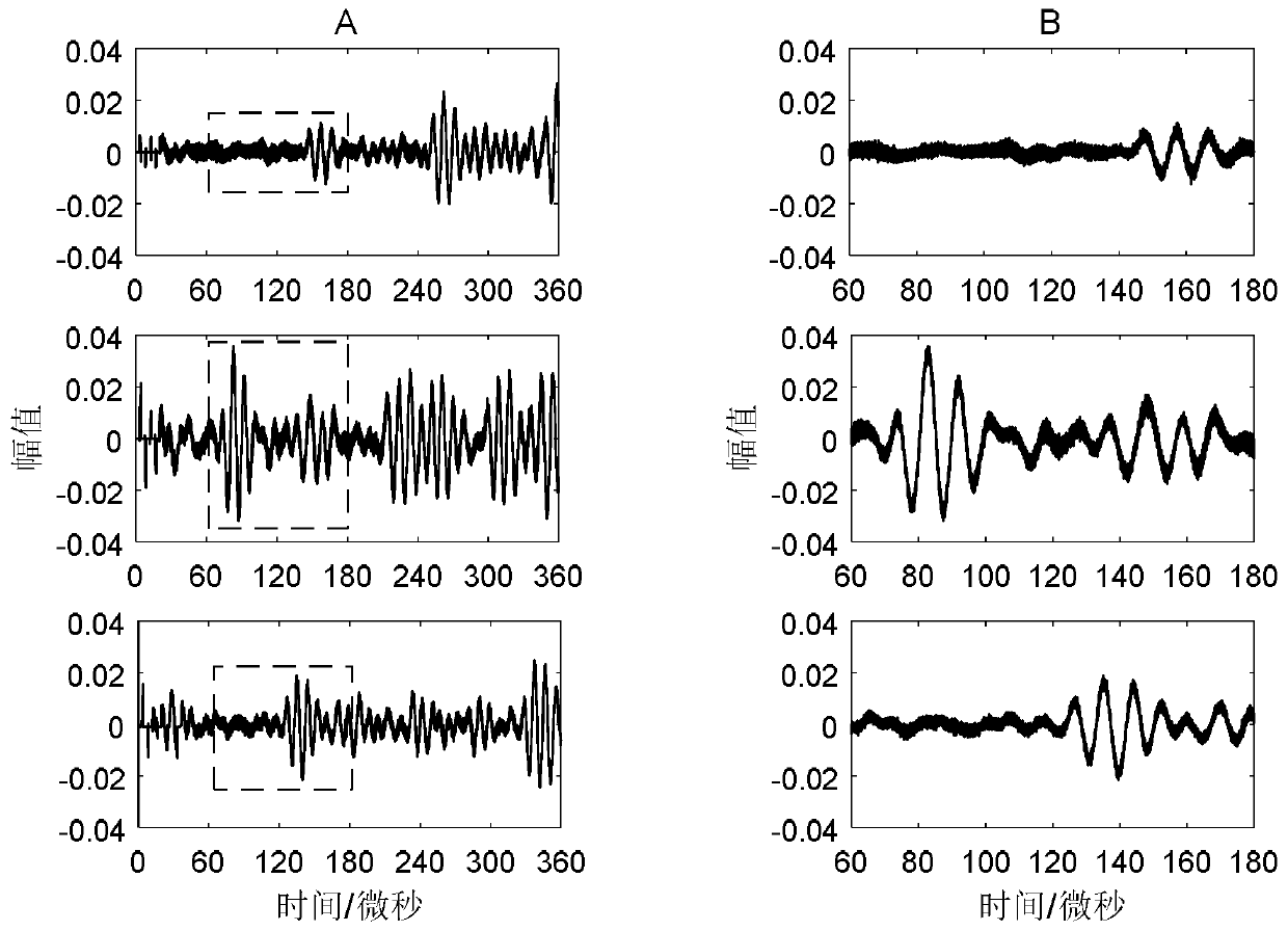
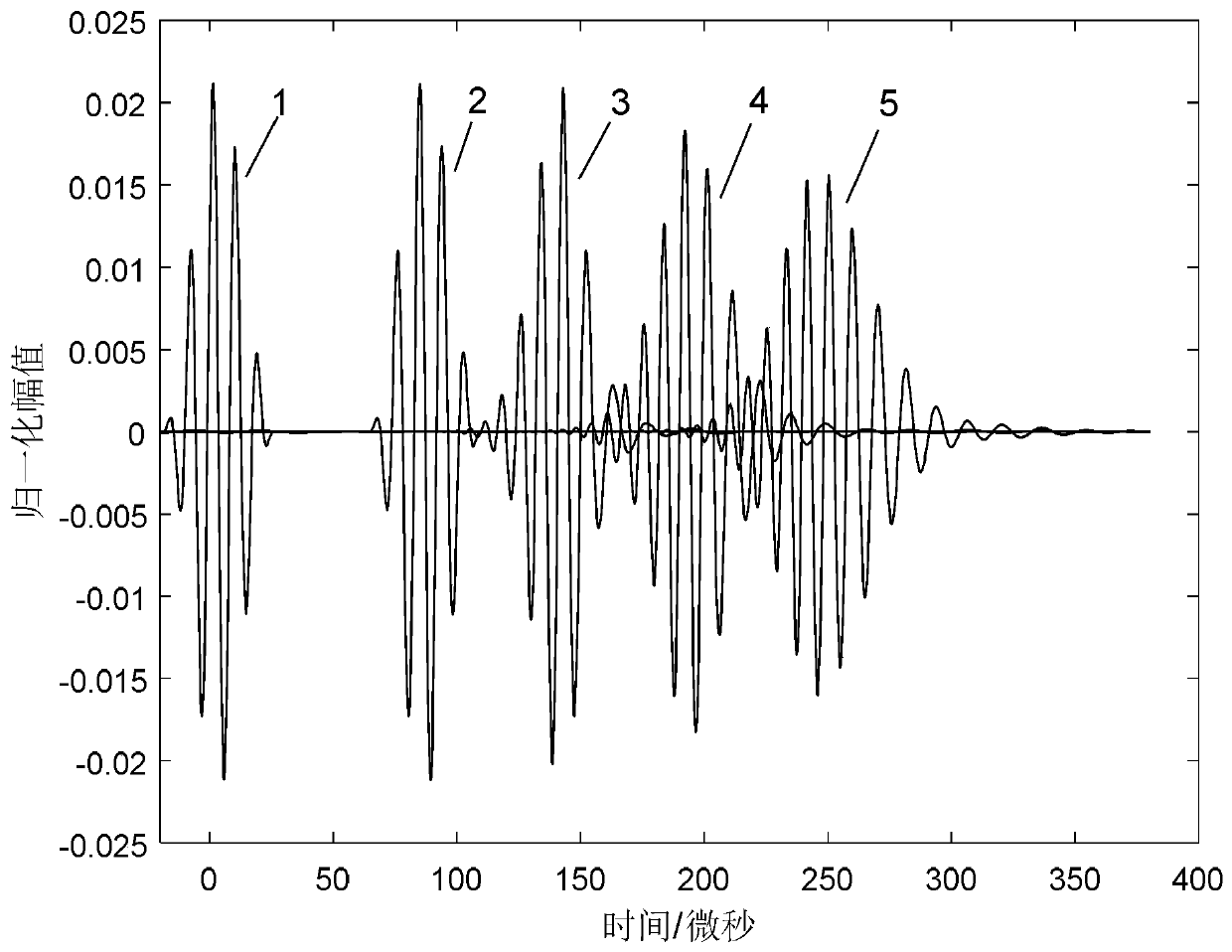
[0028] Specific implementation mode one: refer to Figure 2 to Figure 6 Specifically explaining this embodiment, a two-stage damage location identification method based on guided wave signal sparse decomposition and damage location described in this embodiment includes the following two stages:

[0029] The first stage:

[0030] Step 1: The ultrasonic transducer is excited in the waveguide to be tested to form a 0 and A 0 Modal Lamb wave, setting M collection points on the waveguide to be detected, and collecting the ultrasonic waveguide signal at each collection point;

[0031] Considering the mode conversion at the damage site, the following four Lamb wave packets may exist on the path from the damage to the collection point: the directly propagating S 0 and A 0 Modal, by S 0 converted from A 0 and by A 0 converted to S 0 Mode, considering the dispersion effect of the Lamb wave, the ultrasonic guided wave propagation model can be used to calculate the waveform after ...


PUM


Abstract

A two-stage damage location recognition method based on guided-wave signal sparse decomposition and damage localization relates to the field of ultrasonic non-destructive testing. The present invention aims to resolve a problem that an ultrasonic guided-wave signal analysis result is not accurate enough because a dictionary design method and a signal sparse decomposition algorithm of sparse representation in ultrasonic guided-wave signal overlapping wave packet recognition are not perfect enough. According to the method, a penalty term is used to make coefficient vectors as sparse as possible,a possibility that noise matches dictionary atoms is significantly reduced; a dictionary matrix is designed by using a guided-wave propagation model, wherein problems of guided-wave frequency dispersion, multiplex modes and modal transformation are considered, and an overlapping waveform is recognized in a linear decomposition manner. The method has advantages over a conventional signal processing method. A sparse optimization solution algorithm based on sparse Bayesian learning is used, which has unique advantages in the aspect of handling with under-determined linear problems such as sparserepresentation, and has better robustness for noise.

Description

technical field [0001] The invention belongs to the field of ultrasonic nondestructive testing. Background technique [0002] In the field of civil engineering, ultrasonic nondestructive testing has been widely used in structural damage detection of building structures, bridges, pipelines and so on. With the help of ultrasonic non-destructive testing technology, it is possible to effectively detect whether there is a defect or damage in the structure, locate the defect and estimate the size of the defect, so as to evaluate the safety status of the structure and predict the remaining service life. Compared with vibration-based overall monitoring and a small number of local monitoring technologies in structural health monitoring, ultrasonic nondestructive testing technology can better detect local micro-damages in structures, and is a useful supplement to structural health monitoring technology. The combination of ultrasonic non-destructive testing technology and structural h...

Claims


Application Information

Patent Timeline
Patent Type & Authority Applications(China)
IPC IPC(8): G01N29/44G01N29/04
CPCG01N29/04G01N29/44G01N29/4418G01N29/449G01N2291/0289
Inventor 周文松黄永赵美杰李惠
Owner 哈尔滨工业大学人工智能研究院有限公司
Why Eureka
Try Eureka