A microstructure optical fiber for generating and transmitting vortex light beams

A technology of micro-structured optical fiber and vortex beam, which is applied in the direction of cladding optical fiber, optical waveguide, light guide, etc., can solve the problems of limiting the growth of optical communication capacity, bulky optical modulator, high cost, etc., and achieve good promotion and use value, low nonlinear coefficient, and dispersion flat effect

Pending Publication Date: 2019-12-06
SOUTH CHINA NORMAL UNIVERSITY
View PDF0 Cites 4 Cited by
  • Summary
  • Abstract
  • Description
  • Claims
  • Application Information

AI Technical Summary

Problems solved by technology

In free space, the optical modulator required is bulky, expensive, and needs to be optically coupled in free space
The realization and transmission of vortex light in optical fiber can reduce energy loss and is suitable for long-distance and large-capacity communication. However, in the technical solutions reported so far, the number of OAM modes supported by the optical fiber is limited, which limits the growth of optical communication capacity.

Method used


Image

  • A microstructure optical fiber for generating and transmitting vortex light beams
  • A microstructure optical fiber for generating and transmitting vortex light beams
  • A microstructure optical fiber for generating and transmitting vortex light beams

Examples


Embodiment Construction

[0020] The implementation of the present invention will be described in further detail below in conjunction with the embodiments and accompanying drawings, but the implementation and protection of the present invention are not limited thereto. In the present invention, if there are no specific details below, those skilled in the art can realize or understand with reference to the prior art.

[0021] Embodiments of the present invention are as follows:

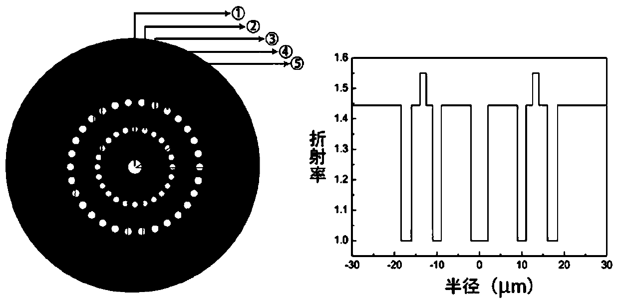
[0022] figure 1 It is a schematic diagram of the cross-section of the optical fiber and a distribution diagram of the refractive index of the cross-section of the optical fiber in the embodiment of the present invention. It includes a central air hole 1 , a second ring of air holes 2 , a high refractive index ring 3 , a third ring of air holes 4 and a cladding 5 . Since the refractive index change of the high-refractive index ring 3 relative to the cladding layer 5 is 0.106, it will be beneficial to separate different eigenmo...


PUM

PropertyMeasurementUnit
Radiusaaaaaaaaaa
Radiusaaaaaaaaaa

Abstract

The invention relates to a microstructure optical fiber for generating and transmitting vortex light beams. A first air circular hole is formed in the center of the cross section. A loop of a plurality of second air circular holes are uniformly formed in the periphery of the first air circular hole; a high-refractive-index circular ring is arranged on the periphery of the loop of second air circular holes, and the inner circumference and the outer circumference of the high-refractive-index circular ring take the circle center of the first air circular holes as the circle center; a loop of a plurality of third air circular holes are uniformly formed in the periphery of the high-refractive-index circular ring; cladding is filled among the first air circular hole, the second air circular holes, the high-refractive-index circular ring and the third air circular holes; the refractive index of the high-refractive-index circular ring is higher than the refractive index of the cladding; and the refractive index of the cladding is higher than the refractive index of the first to third air circular holes. The microstructure optical fiber has the advantages of being low in loss, low in nonlinear coefficient and flat in dispersion, and supports more OAM modes compared with an existing optical fiber.

Description

technical field [0001] The invention relates to the technical field of optical communication and optical fiber, in particular to a microstructure optical fiber for generating and transmitting vortex beams. Background technique [0002] With the increasing penetration rate of the Internet and the faster and faster industrial development, people's requirements for communication speed and capacity are also getting higher and higher. High-speed and high-capacity communication will be the inevitable trend of future communication development. [0003] The speed and capacity of the current traditional communication methods are far from meeting the development of the emerging communication field. In order to improve the capacity of communication, vortex light carrying orbital angular momentum appears in a new multiplexing mode, which solves the capacity problem in traditional multiplexing communication. Therefore, it has been widely concerned by researchers and has become a researc...

Claims


Application Information

Patent Timeline
IPC IPC(8): G02B6/02
CPCG02B6/02304
Inventor 罗爱平马棋昌黄淑鸿
Owner SOUTH CHINA NORMAL UNIVERSITY
Why Eureka
Try Eureka