AI technical title is built by Patsnap AI team. It summarizes the technical point description of the patent document.
A drive system, hybrid technology, applied in electric braking systems, hybrid vehicles, traction driven by engines, etc., can solve the problem of high cost
Pending Publication Date: 2019-12-10
GUANGZHOU AUTOMOBILE GROUP CO LTD
View PDF0 Cites 4 Cited by
Summary
Abstract
Description
Claims
Application Information
AI Technical Summary
This helps you quickly interpret patents by identifying the three key elements:
Problems solved by technology
Method used
Benefits of technology
Problems solved by technology
However, this system requires two independent subsystems, and the cost is high
Method used
Image
Click on the blue label to locate the original text in one second.
Reading with bidirectional positioning of images and text.
Examples
no. 1 example
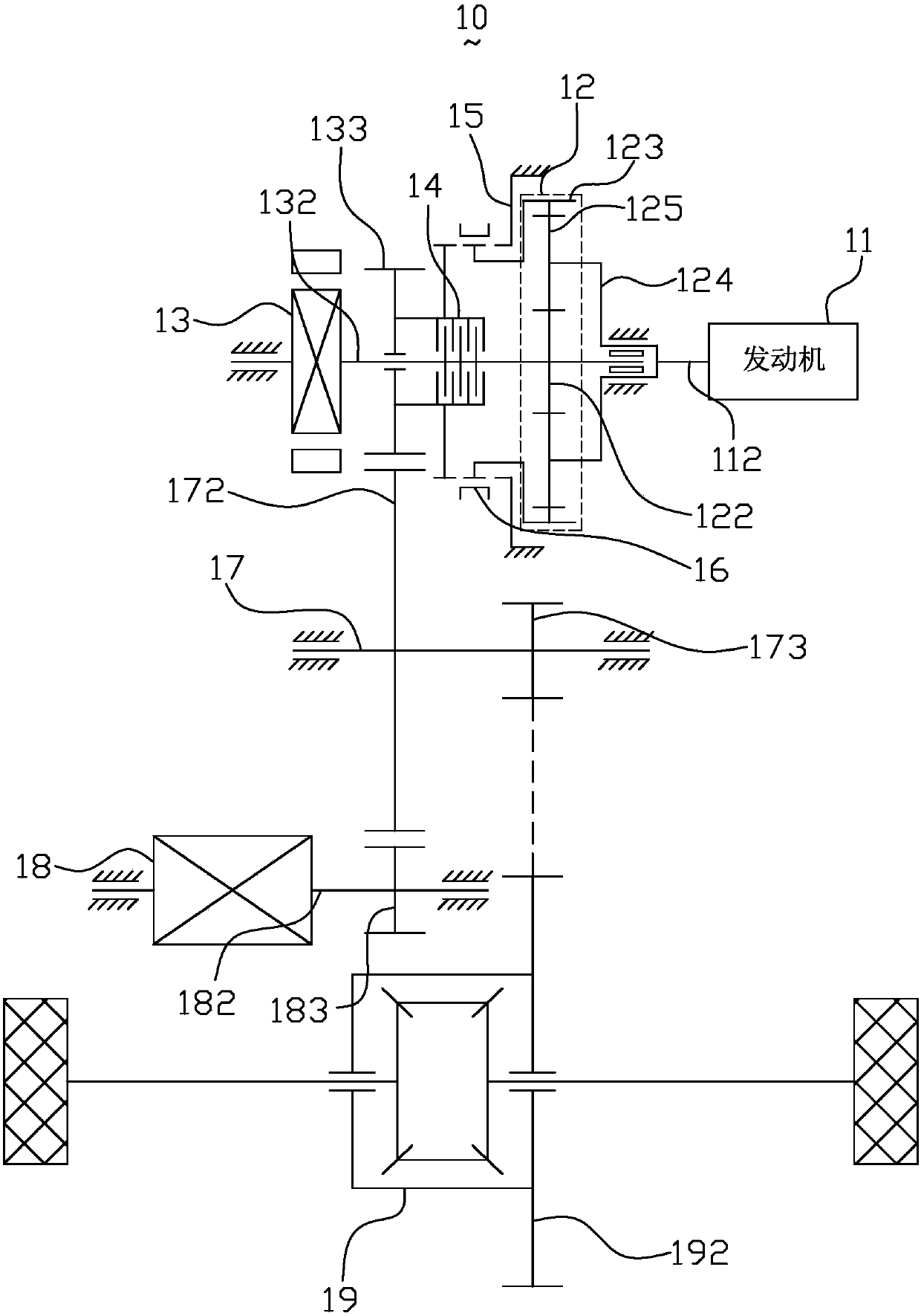
[0042] figure 1 It is a schematic structural diagram of the hybrid drive system according to the first embodiment of the present invention. like figure 1 As shown, the hybrid drive system 10 includes an engine 11, a planetary gear arrangement 12, a first electric machine 13, a clutch gear arrangement, a switch arrangement, an engagement arrangement, an intermediate shaft 17, a second electric machine 18, a differential 19 and a power battery (Fig. not shown).
[0043] The engine 11 has an engine output shaft 112 . In this embodiment, the engine 11 is, for example, a gasoline engine or a diesel engine.
[0044] The planetary gear device 12 includes a first rotation element, a second rotation element, and a third rotation element. The first rotating element is connected to the first motor 13 , the second rotating element is connected to the engine 11 , and the third rotating element is connected to the engagement device 16 . In this embodiment, the first rotation element 12...
no. 2 example
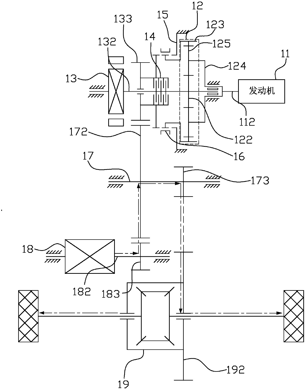
[0068] Figure 11 It is a schematic structural diagram of the hybrid drive system according to the second embodiment of the present invention. like Figure 11 As shown, the structure of the hybrid drive system 10 of this embodiment is substantially the same as that of the hybrid drive system 10 of the first embodiment, and the difference lies in the connection relationship between the engine 11 and the planetary gear device 12 and the connection between the engagement device and the planetary gear device 12 Relationships are different.
[0069] Specifically, in this embodiment, the first rotating element is a sun gear, the second rotating element is a ring gear, the third rotating element is a planet carrier, the engaging device is a synchronizer, and the switching device is a brake or a one-way clutch, that is, Said, the ring gear 123 is connected with the engine output shaft 112, the synchronizer 16 is fixed on the planet carrier 124, the synchronizer 16 includes a left st...
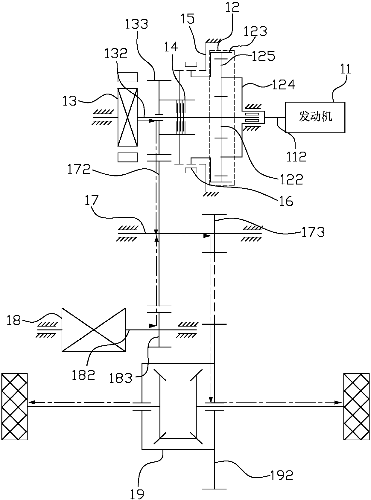
no. 3 example
[0072] The hybrid drive system 10 of the present embodiment has substantially the same structure as the hybrid drive system 10 of the first embodiment, except that the connection relationship between the engine 11 and the planetary gear device 12 and the connection relationship between the engagement device and the planetary gear device 12 are different.
[0073] Specifically, the first rotating element is a planet carrier, the second rotating element is one of the sun gear and the ring gear, the third rotating element is the other of the sun gear and the ring gear, the engaging device is a synchronizer, and the switching device is a brake or a one-way clutch. For the connection relationship and driving method of the components of the hybrid drive system 10, please refer to the first embodiment.
PUM
Abstract
The invention discloses a hybrid power drive system which comprises an engine, a first motor, a second motor, a planetary gear device, a clutch gear device, an engaging device and a switch device; theengine and the first motor are both connected with the planetary gear device; the clutch gear device is arranged between the first motor and the planetary gear device; the planetary gear device comprises a first rotating element, a second rotating element and a third rotating element; the first rotating element is connected with the first motor; the second rotating element is connected with the engine; the third rotating element is connected with the engaging device; the clutch gear device comprises a clutch, a clutch gear and an engaging element; the clutch gear and the engaging element areconnected to the clutch; the clutch gear is connected to the output end; the engaging device is engaged to the third rotating element and the engaging element, or the third rotating element and the switch device or the third rotating element only; the switch device locks or unlocks the third rotating element; and a second motor is connected to the output end. The hybrid power drive system providedby the invention is good in platformization.
Description
technical field [0001] The invention relates to the technical field of new energy, in particular to a hybrid drive system. Background technique [0002] At present, there are two main types of transmissions on the market: stepped transmissions and continuously variable transmissions. Stepped transmissions are subdivided into manual and automatic. Most of them provide a limited number of discrete output to input speed ratios through different meshing arrangements of gear trains or planetary gear trains. The adjustment of the drive wheel speed between two adjacent speed ratios is achieved by the speed change of the internal combustion engine. Continuously variable transmission, whether it is mechanical, hydraulic, or mechanical or electrical, can provide an infinite number of continuously selectable speed ratios within a certain speed range. In theory, the speed change of the driving wheel can be completely completed by the transmission. . In this way, the internal combust...
Claims
Application Information
Patent Timeline
Application Date:The date an application was filed.
Publication Date:The date a patent or application was officially published.
First Publication Date:The earliest publication date of a patent with the same application number.
Issue Date:Publication date of the patent grant document.
PCT Entry Date:The Entry date of PCT National Phase.
Estimated Expiry Date:The statutory expiry date of a patent right according to the Patent Law, and it is the longest term of protection that the patent right can achieve without the termination of the patent right due to other reasons(Term extension factor has been taken into account ).
Invalid Date:Actual expiry date is based on effective date or publication date of legal transaction data of invalid patent.

