
Microwave detection element

A microwave detection and component technology, applied in radio wave measurement systems, material analysis using microwave means, measurement devices, etc., can solve problems such as increasing the power consumption of components, and achieve small size, high detection sensitivity, and low power consumption. Effect

Active Publication Date: 2019-12-10
LANZHOU UNIVERSITY
View PDF0 Cites 3 Cited by
  • Summary
  • Abstract
  • Description
  • Claims
  • Application Information

AI Technical Summary

Problems solved by technology

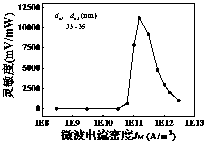
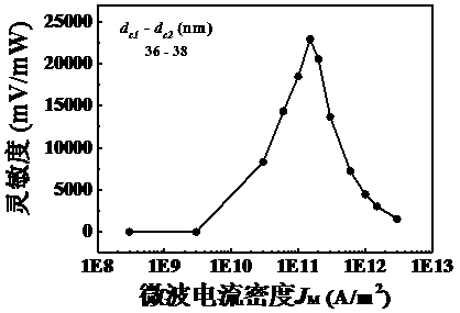
This method has a very high sensitivity, reaching 70000mV / mW, but it needs bias current assistance to achieve such a high sensitivity, and applying bias current assistance will inevitably increase the power consumption of the component; when there is no bias current assistance , the sensitivity value is only about 1000mV / mW

Method used


Image

  • Microwave detection element
  • Microwave detection element
  • Microwave detection element

Examples


Embodiment Construction

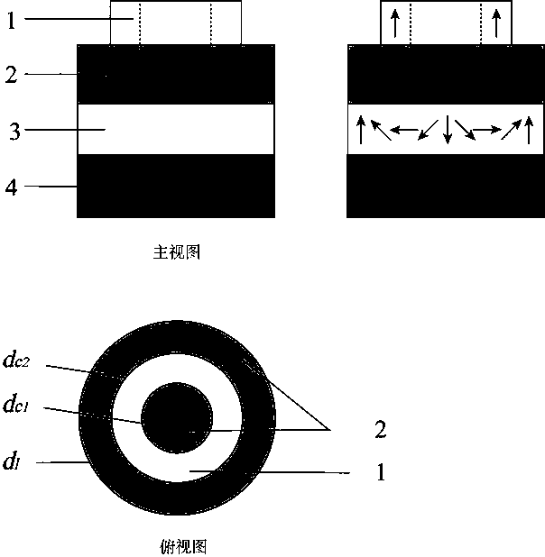
[0026] In order to make the object, technical solution and advantages of the present invention clearer, the present invention will be further described in detail below in conjunction with specific embodiments and accompanying drawings. It should be understood that the specific embodiments described here are only used to explain the present invention, not to limit the present invention.

[0027] The materials used in one embodiment of the present invention are: platinum (Pt) for the heavy metal layer, cobalt iron boron (CoFeB) material for the free layer, cobalt iron boron (CoFeB) material for the pinning layer, and magnesium oxide (MgO) for the insulating layer. ), each layer is formed by vacuum sputtering or vacuum evaporation, and the DM interaction constant between the heavy metal layer and the free layer is 3.0mJ / m 3 , the uniaxial anisotropy constant of the free layer is K = 8.0 × 10 5 J / m 3 , the exchange constant is A = 2.0 × 10 -11 J / m.

[0028] figure 1 It ...


PUM

PropertyMeasurementUnit
Diameteraaaaaaaaaa
The inside diameter ofaaaaaaaaaa
Outer diameteraaaaaaaaaa

Abstract

The invention discloses a microwave detection element which is composed of a sheet pinning layer, an insulating layer, a free layer and a heavy metal layer which are sequentially arranged in a stackedmode, the magnetic pinning layer on the upper layer is annular, and the free layer, the insulating layer and the heavy metal layer are arranged to be circular. Dzyaloshinskii-Moriya interaction can be generated between the heavy metal layer material and the free layer material; magnetic moments in the pinning layer are arranged in the vertical direction, and the magnetic moments in the free layerare arranged in a magnetic skyrmion state due to the Dzyaloshinskii-Moriya interaction. According to the microwave detection element disclosed by the invention, when a microwave current signal is input, the size of the magnetic skyrmion can be periodically changed, the resistance value of the element can also be periodically changed due to the existence of a tunnel magnetoresistance effect, and the microwave detection element can be coupled with the input microwave current to generate a direct-current signal, so that microwave detection is realized. According to the invention, the sensitivityvalue can be greatly improved.

Description

technical field [0001] The invention relates to a microwave detecting element. Background technique [0002] Microwave sensors actually refer to devices or devices that use microwave characteristics to detect some physical quantities. It is mainly divided into a transmitting device and a receiving device. The microwave is emitted by the transmitting device and is absorbed or reflected when encountering the object to be measured, so that the power or frequency of the microwave is changed. The microwave receiving device converts the changed microwave signal into an electrical signal. By analyzing the electrical signal, the physical properties such as the material properties and motion state of the measured object can be obtained, which is the basic principle of microwave detection. Due to the characteristics of non-contact, fast speed, high sensitivity, high temperature and high pressure resistance, and radiation resistance, microwave sensors are widely used in military, tran...

Claims


Application Information

Patent Timeline
IPC IPC(8): G01N22/00G01S7/35H01L43/08H01L43/10
CPCG01N22/00G01S7/352H10N50/85H10N50/10
Inventor 刘青芳王佳宁王金帅王建波
Owner LANZHOU UNIVERSITY
Learn More