Check patentability & draft patents in minutes with Patsnap Eureka AI!

Magnetic feedback DCDC conversion circuit

A technology for converting circuits and circuits, applied in the direction of converting DC power input to DC power output, electrical components, adjusting electrical variables, etc., which can solve the problems of low linearity of optocoupler work, changes in current transmission rate, and influence on loop stability. , to achieve the effect of good radiation resistance, accurate and stable output voltage, and strong stability

Active Publication Date: 2019-12-10
BEIJING RES INST OF PRECISE MECHATRONICS CONTROLS
View PDF5 Cites 0 Cited by
  • Summary
  • Abstract
  • Description
  • Claims
  • Application Information

AI Technical Summary

Problems solved by technology

[0002] As the demand for power supply in the electromechanical servo system is getting higher and higher, the demand for modularization, scalability, and reliability of the power supply for aerospace power supplies is also getting higher and higher; at present, the commonly used isolation methods for switching power supplies are Optocoupler isolation, this method is simple in structure, easy to use and low in cost, but due to the low linearity of the optocoupler itself, under the influence of current, ambient temperature, space radiation and charged particles, its current transmission rate changes further aggravate or even affect the stability of the loop

Method used


Image

  • Magnetic feedback DCDC conversion circuit
  • Magnetic feedback DCDC conversion circuit
  • Magnetic feedback DCDC conversion circuit

Examples


Embodiment 1

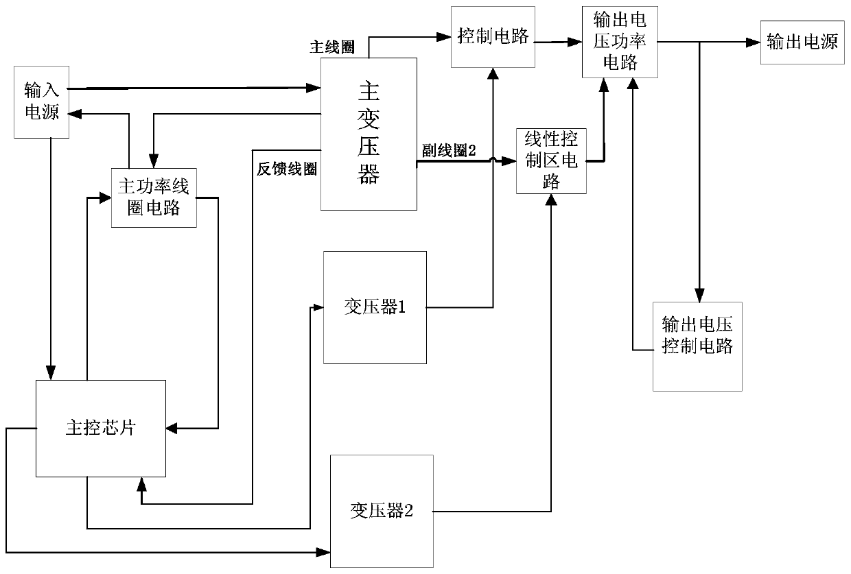
[0031] A magnetic feedback DCDC conversion circuit, comprising: a main transformer, a transformer 1, a transformer 2, a main control chip, a main power coil circuit, a control circuit, an output voltage power circuit, a linear control area circuit, and an output voltage control circuit;

[0032] The external input power supplies power to the main control chip and the main transformer; after the main control chip reaches the starting condition, the main control chip sends a PWM signal to the main power coil of the main transformer through the main power coil circuit, and receives the PWM signal through the main power coil circuit. The current feedback signal of the main transformer, while the main transformer provides an input voltage to the main control chip through the feedback coil of the main transformer; the power supply voltage of the external input power supply to the main control chip is less than the input voltage provided by the main transformer to the main control chip...

Embodiment 2

[0045] The invention relates to a magnetic feedback DCDC conversion circuit, which adopts a voltage and current double-loop control mode. The principle of the technical solution is: use a transformer to isolate the primary side and secondary side of the control circuit, complete the feedback of the error signal on the secondary side through amplitude modulation, and complete the output voltage through the secondary side linear zone control circuit and the output voltage control circuit. Accurate control, and according to the working characteristics of the anti-radiation control chip, the input DC voltage of the primary side is delayed and transformed to drive the secondary side power supply to complete the startup work of the system. When the circuit is started, the voltage transformed by the main transformer The secondary side power supply replaces this part of the function to maintain the system work, such as figure 1 shown.

[0046] It includes a main transformer, a transf...


PUM


Abstract

The invention discloses a magnetic feedback DCDC conversion circuit. A primary side and a secondary side of a control circuit are isolated through a transformer. Feedback of an error signal is completed on the secondary side through amplitude modulation. Output voltage accurate control is completed through a secondary side linear area control circuit and an output voltage control circuit. According to a working characteristic of an anti-radiation control chip, an input direct voltage of the primary side drives a secondary side power supply through time delay and conversion to complete startingwork of a system. After the circuit is started, the secondary side power supply converted by a main transformer replaces the part of functions to maintain the work of the system. Compared with optical coupler isolation, the circuit has higher stability and a better radiation resistance capability, can be well applied to aerospace and an internal portion of an electromechanical servo system, and belongs to the technical field of power supply control.

Description

technical field [0001] The invention relates to a magnetic feedback DC-DC conversion circuit, which belongs to the technical field of power supply control. Background technique [0002] As the demand for power supply in the electromechanical servo system is getting higher and higher, the demand for modularization, scalability, and reliability of the power supply for aerospace power supplies is also getting higher and higher; at present, the commonly used isolation methods for switching power supplies are Optocoupler isolation, this method is simple in structure, easy to use and low in cost, but due to the low linearity of the optocoupler itself, under the influence of current, ambient temperature, space radiation and charged particles, its current transmission rate changes Further aggravate or even affect the stability of the loop. Contents of the invention [0003] The technical problem to be solved by the present invention is: to overcome the deficiencies of the prior a...

Claims


Application Information

Patent Timeline
Patent Type & Authority Applications(China)
IPC IPC(8): H02M3/158
CPCH02M3/1584
Inventor 李春宇王令岩胡骢赵絮王移川
Owner BEIJING RES INST OF PRECISE MECHATRONICS CONTROLS
Features
  • R&D
  • Intellectual Property
  • Life Sciences
  • Materials
  • Tech Scout
  • Unparalleled Data Quality
  • Higher Quality Content
  • 60% Fewer Hallucinations
Learn More