Eureka AIR delivers breakthrough ideas for toughest innovation challenges, trusted by R&D personnel around the world.

External magnetic suspension centrifugal blood pump with central magnetic pole structure

A magnetic pole structure and magnetic levitation technology, which is applied in the technical field of medical equipment, can solve the problems of magnetic levitation rotor impeller instability, hemolysis and other blood damage, magnetic levitation blood damage, etc., to solve the problem of thrombus formation, suppress vibration, and reduce processing difficulty Effect

Pending Publication Date: 2019-12-13
FUWAI HOSPITAL CHINESE ACAD OF MEDICAL SCI & PEKING UNION MEDICAL COLLEGE
View PDF0 Cites 7 Cited by
  • Summary
  • Abstract
  • Description
  • Claims
  • Application Information

AI Technical Summary

Problems solved by technology

[0004] The short-to-medium-term use of ventricular assist pumps in the prior art also has the problem of magnetic suspension control and blood damage caused by the vibration of the rotor impeller: the magnetic suspension rotor impeller in the pump head is unstable under the dynamic load formed by the impact of blood And there is vibration, the vibration will disturb the flow field in the pump, and then aggravate the occurrence of blood damage such as hemolysis in the pump. The unstable and unreliable suspension of the magnetic levitation rotor impeller is also prone to failures that the impeller hits the pump casing and causes the pump to stop.

Method used


Image

  • External magnetic suspension centrifugal blood pump with central magnetic pole structure
  • External magnetic suspension centrifugal blood pump with central magnetic pole structure
  • External magnetic suspension centrifugal blood pump with central magnetic pole structure

Examples


Embodiment Construction

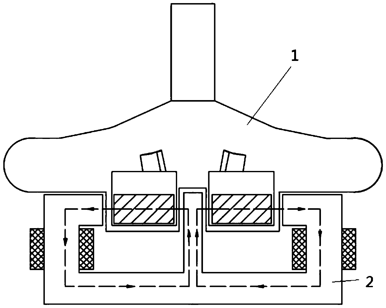
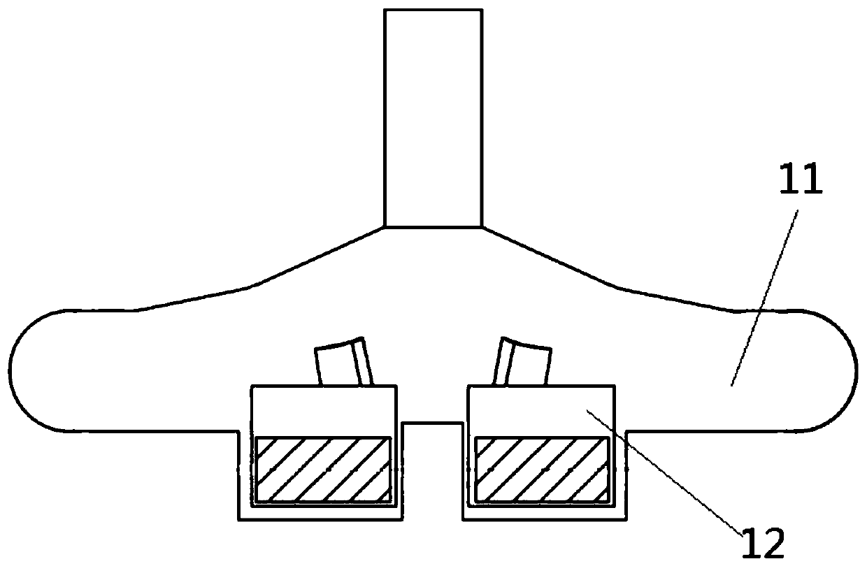
[0053] Such as figure 1 As shown, the external magnetic levitation centrifugal blood pump with a central magnetic pole structure provided by the present invention includes a pump head 1 and a magnetic levitation device 2. The pump head 1 includes a magnetic levitation rotor impeller 12 and a pump housing 11, and the magnetic levitation rotor impeller 12 is located in the pump housing 11. The magnetic levitation rotor impeller 12 includes blades 121, a base 122 and a permanent magnet 123, and there is a gap between the magnetic levitation rotor impeller 12 and the pump casing 11 to serve as a secondary flow channel for scouring.

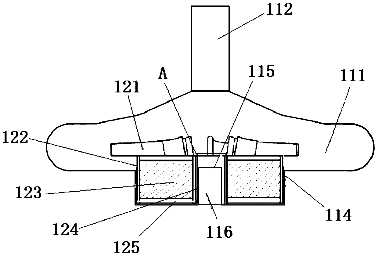
[0054] Such as figure 2 , image 3 with Figure 4 As shown, the pump casing 11 includes a volute 111, a central hole is provided along the central axis on the upper top surface of the volute 111, a central inlet pipe 112 is fixedly connected to the central hole, and the outer edge of the volute 111 is provided The tangential outlet pipe 113 and the lower...


PUM


Abstract

The present invention provides an in vitro magnetic suspension centrifugal blood pump with a central magnetic pole structure, wherein a pump head comprises an impeller and a pump shell, a lower bottomplate of a cylindrical cavity at a lower part of the pump shell is recessed into a central cylindrical shell, and a central tube cavity is formed corresponding to a lower bottom plate outside of thepump shell; blades in the impeller are fixedly arranged on a base seat, the base seat is a cylindrical shell body and a tube section is arranged in the cylindrical shell body, and permanent magnets are fixedly arranged in annular cavities between the tube section and the shell body; the impeller sleeves on a central column shell; a section of a W-shaped secondary flow channel is arranged between the impeller base seat and the pump shell cylindrical cavity, and between the tube section and the central cylindrical shell; and a magnetic suspension device is arranged below the pump shell, stator soft iron in a magnetic suspension element comprises a central cylindrical soft iron and the pump shell central tube cavity is inserted into the central cylindrical soft iron to form a central magneticpole. The centrifugal blood pump can reduce thrombus and hemolysis and improve pump stability and operating efficiency.

Description

Technical field [0001] The present invention relates to the technical field of medical devices, in particular to a magnetic suspension centrifugal blood pump for short- and medium-term use outside the body of a patient, and in particular to a magnetic suspension centrifugal blood pump used for cardiac surgery and cannot be separated from the cardiopulmonary bypass (postoperative cardiogenic shock, congenital heart disease correction Postoperative pulmonary hypertension, post-heart transplantation support), difficult to correct low cardiac output, transition before heart transplantation, failure to achieve spontaneous circulation after cardiopulmonary resuscitation, etc., which require short- and medium-term ventricular assist pump intervention to maintain effective circulation , A non-implantable, external magnetic levitation centrifugal blood pump with a central magnetic pole structure to reduce cardiac work. Background technique [0002] Generally speaking, short and medium-ter...

Claims


Application Information

Patent Timeline
Patent Type & Authority Applications(China)
IPC IPC(8): A61M1/10
CPCA61M60/82A61M60/205A61M60/50
Inventor 胡盛寿柳光茂张岩陈海波
Owner FUWAI HOSPITAL CHINESE ACAD OF MEDICAL SCI & PEKING UNION MEDICAL COLLEGE
Why Eureka
Eureka Blog
Learn More