3D printer

A 3D printer and printing table technology, applied in the field of 3D printing, can solve the problems such as the inability to achieve the smooth effect of the glass iron sheet, the rough surface printing texture, and the inability to remove it, and achieves easy promotion, low manufacturing costs, and reduced maintenance costs. Effect

Inactive Publication Date: 2019-12-13
FOSHAN UNIVERSITY
View PDF8 Cites 1 Cited by
  • Summary
  • Abstract
  • Description
  • Claims
  • Application Information

AI Technical Summary

Problems solved by technology

Among them, although glass and iron sheets can print a smooth bottom surface, they have the following disadvantages: 1. Need to apply solid glue or textured paper before printing
2. After printing, you need to use a spatula to remove the model, which is easy to hurt your hands
3. It is difficult to disassemble and assemble, either it can be removed by buckle, or it cannot be removed
Although the flexible frosted hot bed sticker does not need to be coated with solid glue and textured paper, it is also easy to disassemble, but its surface printing texture is rough, and it cannot achieve the smooth effect of glass iron sheet

Method used


Image

  • 3D printer
  • 3D printer
  • 3D printer

Examples


Embodiment 1

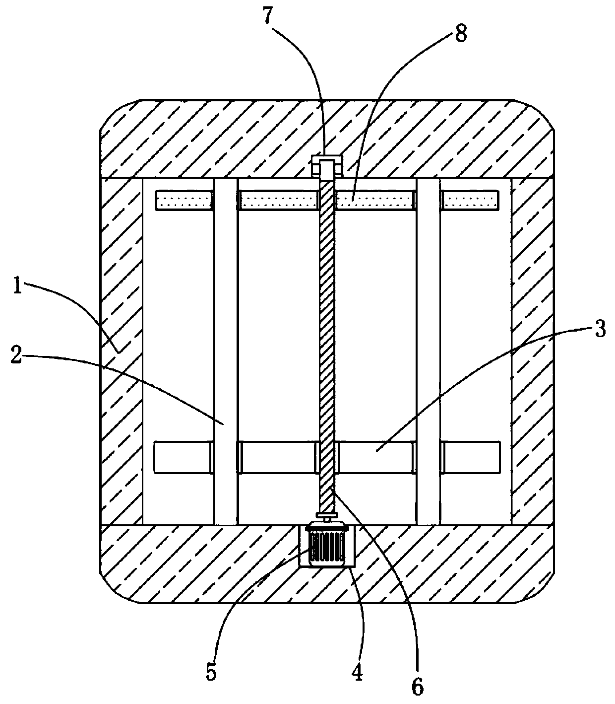
[0036] Such as Figure 1~5 A 3D printer is shown, which includes a housing; two optical axes are symmetrically and fixedly installed in the housing, and the same printing platform is slidably installed on the two optical axes; a heating bed for carrying products is provided on the printing platform; The side is provided with the print nozzle 17 facing the hot bed, and the hot bed includes a contact layer 18, a glued layer group and a magnetic magnetic paste layer 19 that are superimposed on top and bottom and are used to provide adsorption force; the contact layer 18 has a smooth surface One side of the model is the contact surface.

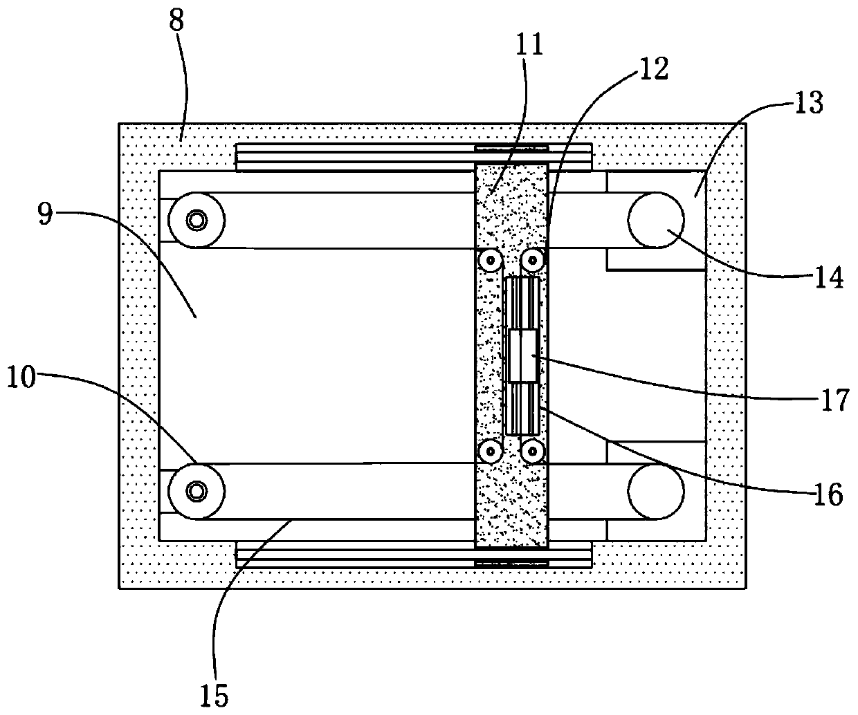
[0037] Among them, such as Figure 4~5 As shown, in this embodiment 1, the contact layer 18 is made of transparent PEI material, and its thickness is 0.45mm;

[0038] In the embodiment 1, a contact layer 18 , an upper glue layer 20 , a rubber layer 21 , a lower glue layer 22 , and a magnetism-providing magnetic layer 19 are arranged sequentiall...

Embodiment 2

[0047] Such as Figure 1~5 A 3D printer is shown, which includes a housing; two optical axes are symmetrically and fixedly installed in the housing, and the same printing platform is slidably installed on the two optical axes; a heating bed for carrying products is provided on the printing platform; The side is provided with the print nozzle 17 facing the hot bed, and the hot bed includes a contact layer 18, a glued layer group and a magnetic magnetic paste layer 19 that are superimposed on top and bottom and are used to provide adsorption force; the contact layer 18 has a smooth surface One side of the model is the contact surface.

[0048] Among them, such as Figure 4~5 As shown, in this embodiment 1, the contact layer 18 is made of transparent PEI material, and its thickness is 0.45mm;

[0049] In Example 2, a contact layer 18 , an upper glue layer 20 , a rubber layer 21 , a lower glue layer 22 , and a magnetism-providing magnetic paste layer 19 are arranged sequentially...


PUM

PropertyMeasurementUnit
thicknessaaaaaaaaaa

Abstract

The invention discloses a 3D printer. The 3D printer comprises a shell, wherein two optical shafts are symmetrically and fixedly installed in the shell, and the same printing table is installed on thetwo optical shafts in a sliding mode; a hot bed for bearing products is arranged on the printing table; a printing nozzle which faces the hot bed is arranged above the hot bed; the hot bed comprisesa contact layer and gluing layer group which is arranged in an overlapping mode up and down and is used for providing the adsorption force and of which the surface is smooth and a magnet layer which is used for providing magnetism; and the smooth surface of the contact layer is the contact surface of a model. The 3D printer has the advantages that the structure is simple, the manufacturing cost islow, the use barrier of a user is low, the effect that the surface of the hot bed can be as smooth as the surface of a glass iron sheet is achieved, the model is convenient to remove, and solid gum and masking paper do not need to be applied.

Description

technical field [0001] The present invention relates to the technical field of 3D printing, in particular to a 3D printer. Background technique [0002] 3D printing is a kind of rapid prototyping technology. It is a technology based on digital model files and using bondable materials such as powdered metal or plastic to construct objects by layer-by-layer printing. 3D printing is usually realized by using digital technology material printers. It is often used to manufacture models in mold manufacturing, industrial design and other fields, and is gradually used in the direct manufacturing of some products. There are already parts printed using this technology . The technology has applications in jewelry, footwear, industrial design, architecture, engineering and construction (AEC), automotive, aerospace, dental and medical industries, education, geographic information systems, civil engineering, firearms, and others. [0003] At present, the mainstream 3D printing technolog...

Claims


Application Information

Patent Timeline
Patent Type & Authority Applications(China)
IPC IPC(8): B29C64/118B29C64/227B29C64/393B33Y30/00B33Y50/02
CPCB33Y30/00B33Y50/02B29C64/118B29C64/227B29C64/393
Inventor 陈炫玮
Owner FOSHAN UNIVERSITY
Why Eureka
Try Eureka