Hot air fiber forming system for rock wool production

An air-forming and hot-air technology, which is applied in the field of rock wool fiber-forming technology and equipment, can solve the problems of small fiber diameter, high fiber-forming rate, and low slag ball content, and achieves small fiber diameter and high fiber-forming rate. , the effect of less slag balls

Inactive Publication Date: 2019-12-13
CHINA SHIP SCIENTIFIC RESEARCH CENTER (THE 702 INSTITUTE OF CHINA SHIPBUILDING INDUSTRY CORPORATION)
View PDF5 Cites 1 Cited by
  • Summary
  • Abstract
  • Description
  • Claims
  • Application Information

AI Technical Summary

Problems solved by technology

[0007] Aiming at the shortcomings in the above-mentioned existing production technology, the applicant provides a hot-air fiber-forming system for rock wool production, which effectively solves the defects caused by the existing room-temperature blown-off wind rock wool fiber-forming technology, and enables The fiber-forming fiber diameter is small, the content of slag balls is small, the fiber-forming rate is high, and it is more energy-saving and environmentally friendly

Method used


Image

  • Hot air fiber forming system for rock wool production
  • Hot air fiber forming system for rock wool production
  • Hot air fiber forming system for rock wool production

Examples


Embodiment Construction

[0040] The specific implementation manner of the present invention will be described below in conjunction with the accompanying drawings.

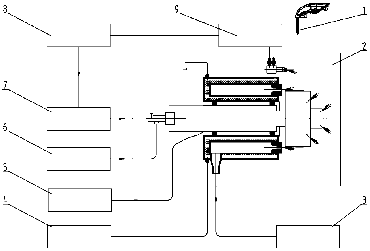
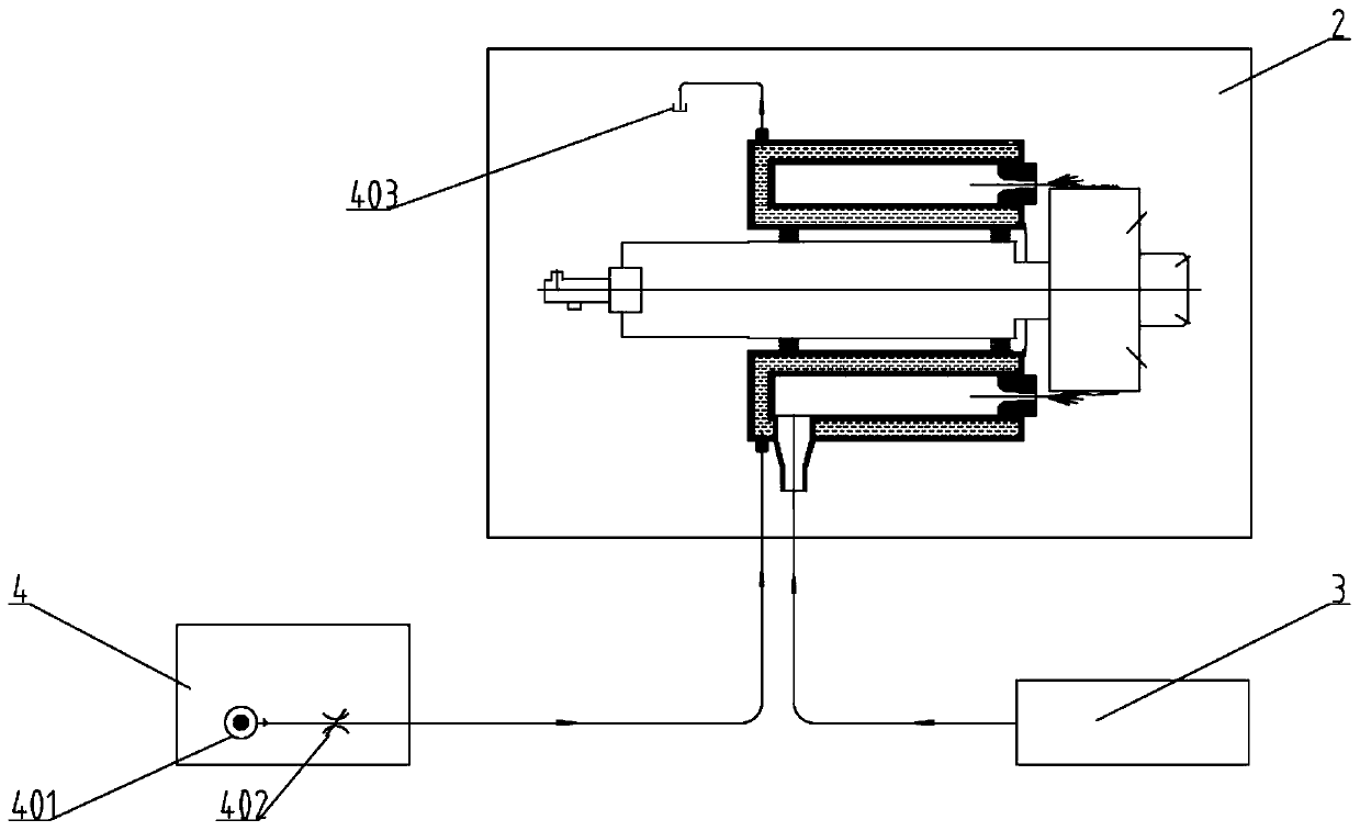
[0041] Such as Figure 1-Figure 8 As shown, the hot-air fiber-forming system for rock wool production in this embodiment includes a high-temperature hot-air fiber-forming four-roller centrifuge 2,

[0042] The structure of the high-temperature hot-air fiber-forming four-roller centrifuge 2 is: a casing 212, four main shafts 204 arranged in parallel and spaced inside the casing 212, and a centrifugal roller 208 is installed on each main shaft 204, and the installation form of each centrifugal roller 208 is the same , taking one of the centrifugal rollers 208 as an example, its specific installation structure is: the centrifugal roller 208 is installed on the main shaft 204 through the bearing 207, the cooling water jacket 206 is arranged on the outside of the centrifugal roller 208, and the cooling water jacket 206 is connected to cooling ...


PUM


Abstract

The invention discloses a hot air fiber forming system for rock wool production. The hot air fiber forming system comprises a high-temperature hot air fiber forming four-roller centrifugal machine, and also comprises a liquid-gas mixing center glue spraying device, a centrifugal roller cooling water system, an oil-gas lubricating system, a heat insulation cooling system and a high-temperature high-speed hot air system which are arranged in parallel; an output end of the liquid-gas mixing center glue spraying device is communicated with a center glue spraying inlet through a pipeline; an outputend of the centrifugal roller cooling water system is communicated with a cooling water inlet through a pipeline, the oil-gas lubricating system is communicated with a cavity in a main shaft througha pipeline, the heat insulation cooling system is communicated with a heat insulation cooling water inlet through a pipeline, and the high-temperature high-speed hot air system is communicated with ablow-off air port through a pipeline. The hot air fiber forming system further comprises a glue applying system, the glue applying system is communicated with the liquid-gas mixing center glue spraying device and a peripheral glue applying device through pipelines, the peripheral glue applying device is connected with a spray head, glue is sprayed to the periphery of a centrifugal roller, and mistglue flow is formed. According to the system, fiber forming fiber is small in diameter, low in slag ball content, high in fiber forming rate and more energy-saving and environment-friendly.

Description

technical field [0001] The invention relates to the technical field of rock wool fiber-forming technology and equipment, in particular to a hot-air fiber-forming system for rock wool production. Background technique [0002] In the rock wool production process, the rock wool fiber-forming system is the key process of rock wool fiber production, and the fiber-forming system determines the fiber production, fiber diameter, slag ball content, and uniformity of fiber spray glue in rock wool production. [0003] Fiber-forming principle of rock wool production: [0004] The main raw material is basalt rock, which is melted at high temperature in a melting furnace. After the melt stream flows to the centrifugal roller, it is dispersed into a ring shape. Under the action of centrifugal force, the ring-shaped melt is pressed to the outer edge of the roller wheel. At this time, the thickness of the melt layer is reduced to the surface capacity of the melt itself. A certain limit is ...

Claims


Application Information

Patent Timeline
Patent Type & Authority Applications(China)
IPC IPC(8): C03B37/00
CPCC03B37/00
Inventor 张志刚郑剑锋刘志恒褚旭东孙刚陈鹏纪飞李玉山
Owner CHINA SHIP SCIENTIFIC RESEARCH CENTER (THE 702 INSTITUTE OF CHINA SHIPBUILDING INDUSTRY CORPORATION)
Why Eureka
Try Eureka