Scaffold for building construction bearing
A technology for building construction and scaffolding, which is applied in the connection of scaffolding, construction, building structure, etc., can solve the problems of difficulty in matching the pipe fittings and connecting parts of the scaffolding, increase the friction force of the scaffolding connecting parts, increase the construction cost, etc. Stable performance, reduced oxidation chance, reduced fixation effect
- Summary
- Abstract
- Description
- Claims
- Application Information
AI Technical Summary
Problems solved by technology
Method used
Image

Examples
Embodiment approach 1
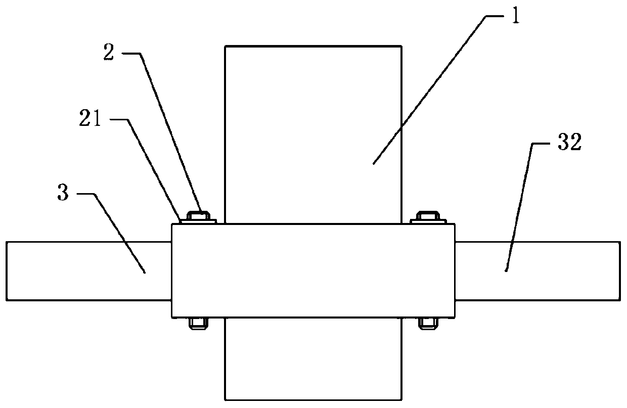
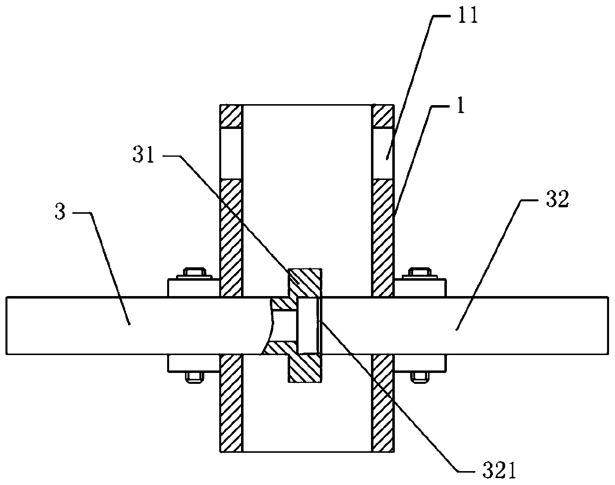
[0038] Embodiment 1: Weld the main connecting piece 4 and the auxiliary connecting piece 4 on the main shaft 1, so that the mounting holes 11 correspond to the fixing holes one by one, and then pass the T-shaped limiter of the main pipe 3 horizontally through the fixing holes and the mounting holes 11, then turn the main pipe 3 as attached figure 2 In the state shown, that is, the T-shaped stopper rotates vertically, and then the auxiliary pipe 32 is inserted into the main shaft 1 through the fixing hole and the installation hole 11, and the left end of the auxiliary pipe 32 is inserted into the concave of the stopper. In the groove, and the secondary pipe 32 is tapered with the limiting member, and the deformation of the expansion ring 321 is used to block the gap between the two, so as to reduce the air entering the connection position between the limiting member and the auxiliary pipe 32.
[0039] Then pass the fastening bolt 2 through the limit hole and the fastening hol...
Embodiment approach 2
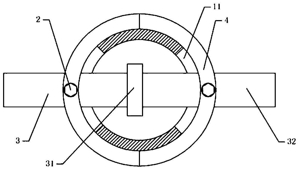
[0040] Embodiment 2: choose a certain angle to install the main pipe 3 and the auxiliary pipe 32, and the installation method is: select the angle at which the main pipe 3 or the auxiliary pipe 32 needs to be installed.
[0041] Turn the main connecting piece 4 to a certain angle, then weld the main connecting piece 4 on the main shaft 1, and then weld the auxiliary connecting piece 4 on the main shaft 1, and ensure the fixing hole of the main connecting piece 4 and the auxiliary connecting piece 4. Align the fixing holes. to attach image 3 For example, the main pipe 3 and the auxiliary pipe 32 are rotated 5° counterclockwise, and then the main pipe 3 and the auxiliary pipe 32 are installed according to Embodiment 1, so as to change the angle of the main pipe 3 and the auxiliary pipe 32, so as to achieve the main pipe from multiple angles 3 and secondary pipe 32 for the purpose of installation. In this way, when faced with a non-right angle or non-180° installation environm...
Embodiment approach 3
[0042]Embodiment 3: choose a certain angle to install the main pipe 3 and the auxiliary pipe 32, and the installation method is: select the angle at which the main pipe 3 or the auxiliary pipe 32 needs to be installed.
[0043] Turn the main connecting piece 4 to a certain angle, then weld the main connecting piece 4 on the main shaft 1, and then move the auxiliary connecting piece 4 to a certain angle, and then weld it on the main shaft 1. For example: the main connecting piece 4 rotates 5° clockwise, and the secondary connecting piece 4 rotates 5° counterclockwise. Extend the main pipe 3 and the auxiliary pipe 32 into the main shaft 1 to offset each other, and then fix the main pipe 3 and the auxiliary pipe 32 by fastening the bolt 2 according to the first embodiment, so that the auxiliary pipe 32 and the main pipe 3 have a certain angle , to achieve the purpose of changing the angle of the main pipe 3 and the secondary pipe 32.
PUM
 Abstract
Description
Claims
Application Information
 - R&D
- Intellectual Property
- Life Sciences
- Materials
- Tech Scout
- Unparalleled Data Quality
- Higher Quality Content
- 60% Fewer Hallucinations
Browse by: Latest US Patents, China's latest patents, Technical Efficacy Thesaurus, Application Domain, Technology Topic, Popular Technical Reports.
© 2025 PatSnap. All rights reserved.Legal|Privacy policy|Modern Slavery Act Transparency Statement|Sitemap|About US| Contact US: help@patsnap.com