Refrigerant charge determination method of refrigeration system and refrigeration system

A refrigeration system and refrigerant technology, applied in refrigerators, refrigeration components, refrigeration and liquefaction, etc., can solve the problems of explosives, reduce the charge amount of ammonia refrigeration system, toxicity, etc.

A refrigeration system and refrigerant technology, applied in refrigerators, refrigeration components, refrigeration and liquefaction, etc., can solve the problems of explosives, reduce the charge amount of ammonia refrigeration system, toxicity, etc.

CN110567207AInactive Publication Date: 2019-12-13广州市粤联水产制冷工程有限公司

Image

  • Refrigerant charge determination method of refrigeration system and refrigeration system
  • Refrigerant charge determination method of refrigeration system and refrigeration system
  • Refrigerant charge determination method of refrigeration system and refrigeration system

Examples


Embodiment 1

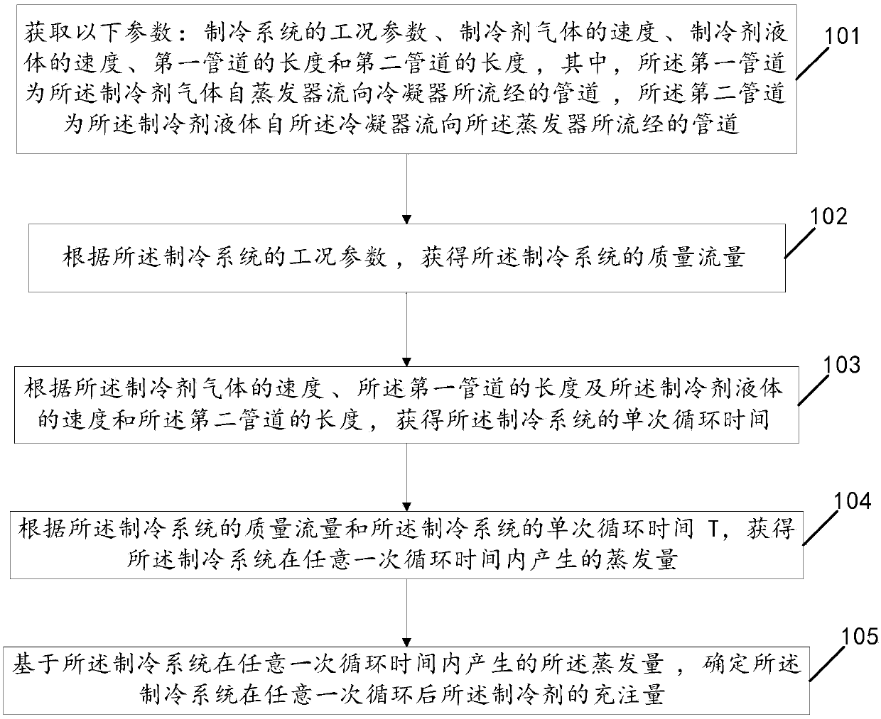
[0066] Please also refer to Figure 1 to Figure 3 , figure 1 It is a schematic flow chart of the method for determining the refrigerant charging amount of the refrigeration system provided by Embodiment 1 of the present invention; figure 1 As shown, a method for determining the refrigerant charge of a refrigeration system may include:

[0067] 101. Obtain the following parameters: operating condition parameters of the refrigeration system, velocity V of the refrigerant gas 1 , The velocity V of the refrigerant liquid 2 , the length L of the first pipeline 1 and the length L of the second pipe 2 , wherein the first pipeline is a pipeline through which the refrigerant gas flows from the evaporator to the condenser, and the second pipeline is a pipeline through which the refrigerant liquid flows from the condenser to the evaporator.

[0068] In the embodiment of the present invention, the working condition parameters of the refrigeration system include the refrigeration capa...

Embodiment 2

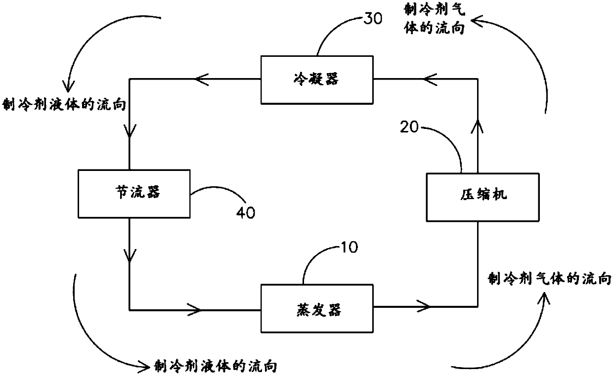
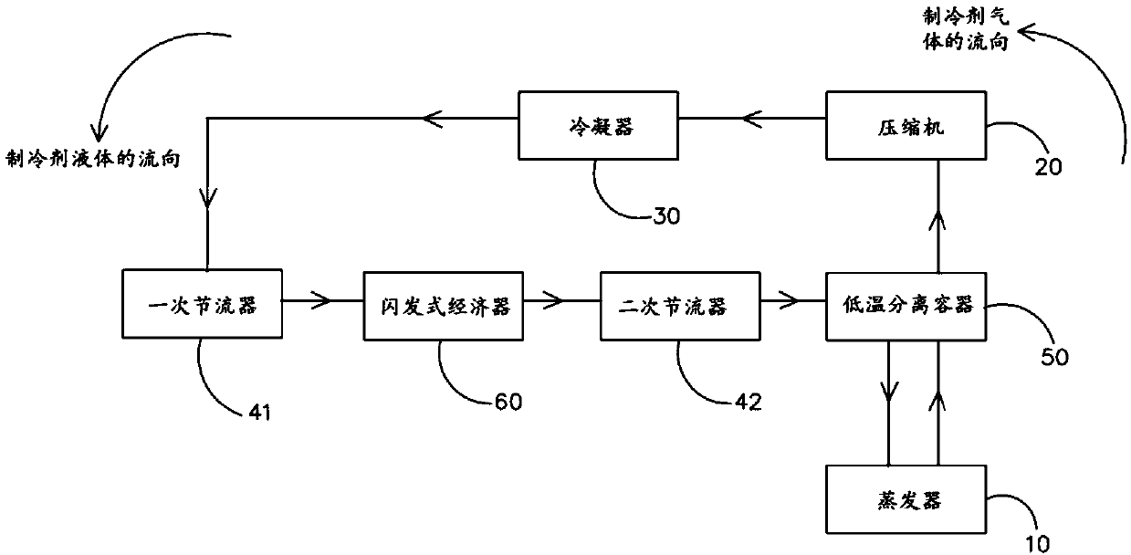
[0097] Please also refer to Figure 4 and Figure 5 A refrigeration system provided by Embodiment 2 of the present invention includes an evaporator 10, a compressor 20, a condenser 30, a liquid storage pipe 70, and a restrictor 40, and the compressor 20 is connected to the outlet of the evaporator 10 through pipelines. Gas port, the condenser 30 is connected to the compressor 20, one end of the liquid storage pipe 70 is connected to the condenser 30, and the restrictor 40 is connected to the other end of the liquid storage pipe 70. One end of the device 40 away from the liquid storage pipe 70 is connected to the liquid inlet pipe of the evaporator 10; wherein the liquid storage pipe 70 is used to store the refrigerant liquid and provide the refrigerant liquid to the evaporator 10, and the storage The liquid capacity of the liquid pipe 70 is determined by the charging amount of the refrigerant after any cycle of the refrigeration system determined by the method of the first em...


PUM


Abstract

The invention discloses a refrigerant charge determination method of a refrigeration system. The method comprises the following steps that working condition parameters of the refrigeration system, thespeed of refrigerant gas, the speed of refrigerant liquid, the length of a first pipeline and the length of a second pipeline are acquired, wherein the first pipeline is a pipeline through which therefrigerant gas flows from an evaporator to a condenser, and the second pipeline is a pipeline through which the refrigerant liquid flows from the condenser to the evaporator; the mass flow rate of the refrigeration system is acquired according to the working condition parameters of the refrigeration system; the single cycle time of the refrigeration system is acquired according to the speed of the refrigerant gas, the speed of the refrigerant liquid, the length of the first pipeline and the length of the second pipeline; the evaporation amount of the refrigeration system in any one-time cycletime is acquired according to the mass flow rate and the single cycle time; and the refrigerant charge after each cycle is determined based on the evaporation amount. According to the method, the charge can be quickly determined, and the charge of the refrigeration system can be accurately controlled.

Description

technical field [0001] The invention relates to the technical field of refrigeration cycles, in particular to a method for determining the refrigerant charging amount of a refrigeration system and the refrigeration system. Background technique [0002] At present, compared with carbon dioxide refrigerant and freon refrigerant, ammonia refrigerant has the advantages of simple preparation process, low price, no damage to the ozone layer, no greenhouse effect, large latent heat of vaporization, high refrigeration and heat release coefficient, etc., and is widely used in Large-scale cold storage, supermarket food display cabinets and other places. However, due to the disadvantages of ammonia refrigerants such as toxicity (low value) and explosiveness, for safety considerations, my country has certain requirements for the amount of ammonia refrigerant in the refrigeration system, specifically to meet the requirements of system operation. In the case of the situation, reduce the c...

Claims


Application Information

Patent Timeline
13 Dec 2019
Publication
CN110567207A
IPC
F25B45/00; F25B49/02
CPC
F25B45/00; F25B49/02
Inventors
李宪光