
Three-phase three-level ANPC common-mode current elimination inverter system

A common-mode current, inverter system technology, applied in the direction of converting AC power input to DC power output, electrical components, output power conversion devices, etc. Problems such as circuits and inductors easy to saturate

Active Publication Date: 2019-12-13
HEFEI UNIV OF TECH
View PDF4 Cites 0 Cited by
  • Summary
  • Abstract
  • Description
  • Claims
  • Application Information

AI Technical Summary

Problems solved by technology

[0005] 1) When the second common-mode inductor uses a high-permeability magnetic core, the inductor is easily saturated;
[0006] 2) The common-mode parasitic capacitance of the uncertain DC power supply to the ground is not considered, that is, the influence of the common-mode parasitic capacitance of the photovoltaic array to the ground on the common-mode current suppression;
[0007] 3) In order to obtain a good common-mode current suppression effect at low frequencies, the required second common-mode inductance has a large parameter value and a large volume
[0009] 1) This circuit is not suitable for high-frequency inverter circuits;
[0010] 2) The inverter circuit is aimed at two-level circuits and is difficult to apply to three-level circuits;
[0011] 3) The common-mode parasitic capacitance of the uncertain DC power supply to the ground is not considered, that is, the influence of the common-mode parasitic capacitance of the photovoltaic array to the ground on the common-mode current suppression

Method used


Image

  • Three-phase three-level ANPC common-mode current elimination inverter system
  • Three-phase three-level ANPC common-mode current elimination inverter system
  • Three-phase three-level ANPC common-mode current elimination inverter system

Examples


Embodiment Construction

[0049] In order to make the purpose and technical solution of the present invention clearer, the specific implementation manners of the present invention will be further described in detail below in conjunction with the accompanying drawings and embodiments.

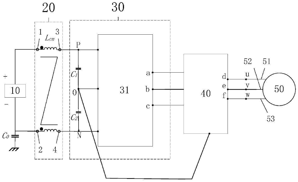
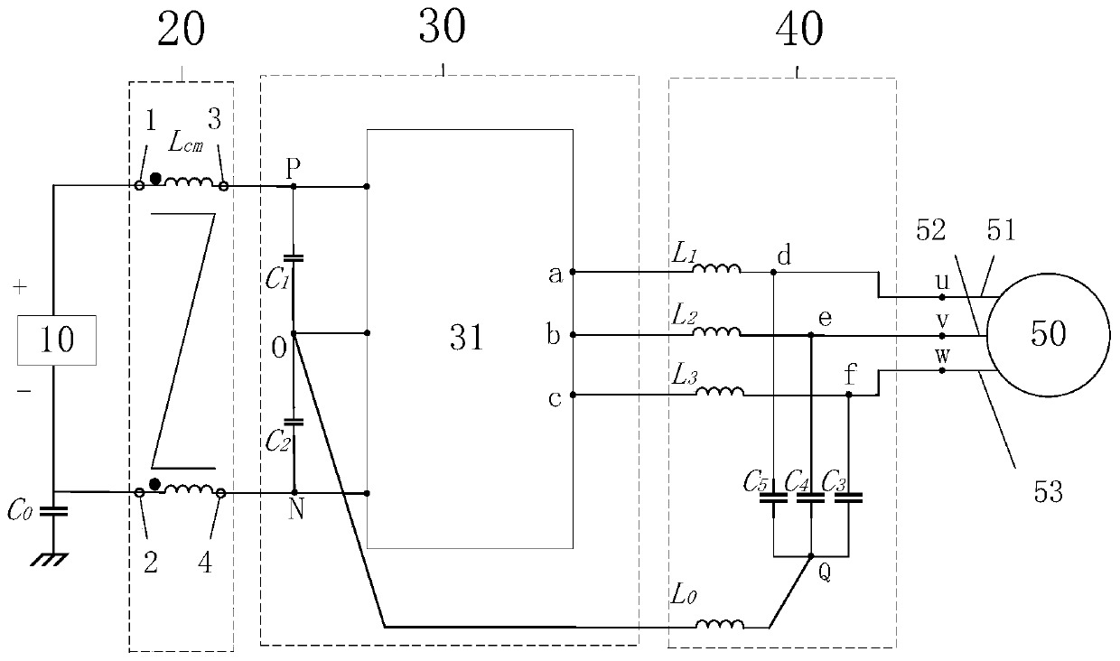
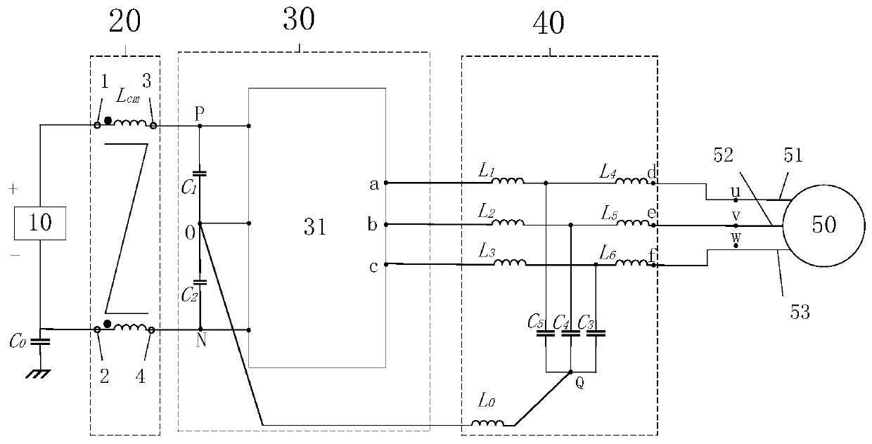
[0050] figure 1 It is a topological diagram of a three-phase three-level ANPC elimination common mode current inverter system of the present invention, Figure 4 is the circuit diagram of inverter main circuit 31 of the present invention, by figure 1 and Figure 4 It can be seen that a three-phase three-level ANPC common-mode current elimination inverter system of the present invention includes a DC power supply 10 , a DC side circuit 20 , a three-phase three-level ANPC inverter circuit 30 , a filter circuit 40 and a load 50 .

[0051] The three-phase three-level ANPC inverter circuit 30 includes two identical supporting capacitors, a positive DC bus P, a negative DC bus N, a midpoint O of the DC bus, and an inverter m...


PUM


Abstract

The invention discloses a three-phase three-level ANPC common-mode current elimination inverter system. The system comprises a DC power supply, a DC side circuit, a three-phase three-level ANPC inverter circuit, a filter circuit and a load. The DC power supply includes a DC power supply to ground common-mode parasitic capacitor. The DC side circuit includes a common mode inductor. The three-phasethree-level ANPC inverter circuit includes an inverter main circuit and two identical support capacitors. The filter circuit includes three identical filter inductors, three identical filter capacitors and an inductor pulled back to the midpoint of a DC bus. The load includes three AC buses. The inverter system provided by the invention has low cost and small occupied volume of added auxiliary components, can eliminate the influence of uncertain parasitic capacitance parameters of the DC power supply under high frequency conditions, and realizes effective common-mode current elimination.

Description

technical field [0001] The invention relates to the field of power electronic converters, in particular to a three-phase three-level ANPC elimination common-mode current inverter system. Background technique [0002] In the inverter system, common-mode parasitic capacitance to ground commonly exists in the DC power supply. Uncertain common-mode parasitic capacitance to ground is bound to have an impact on inverter performance, which is especially serious in photovoltaic inverters. The non-isolated photovoltaic grid-connected power generation method without a transformer has quickly gained the attention of scientific researchers and industrial circles in various countries by virtue of its absolute advantages of high change efficiency, small size, light weight and low cost, and has been applied in some European countries. . However, because there is no transformer as isolation, the photovoltaic cells, photovoltaic inverters, and the grid form a common-mode loop through the c...

Claims


Application Information

Patent Timeline
IPC IPC(8): H02M7/483H02M1/12
CPCH02M1/12H02M7/483H02M1/123
Inventor 王佳宁刘晓晖彭强
Owner HEFEI UNIV OF TECH
Learn More