High-stress impact burst roadway anchor rod, design method and work method

A technology of rock burst and high stress, which is applied in the installation of bolts, calculations, mining equipment, etc., can solve the problems of high pre-tightening force, reduced bearing capacity, low anchoring force, etc., and achieve high anchoring force and high pre-tightening force Effect

Active Publication Date: 2019-12-17
CHINA UNIV OF MINING & TECH
View PDF12 Cites 7 Cited by
  • Summary
  • Abstract
  • Description
  • Claims
  • Application Information

AI Technical Summary

Problems solved by technology

[0006] Whether it is a resin coil anchor or a mechanical inverted wedge anchor, the allowable deformation is only the elongation of the rod body, which cannot meet the large deformation and impact resistance requirements of the high-stress impact rock roadway
[0007] Although the expansion shell anchor can provide anchoring force through the friction between the rod body and the hole wall, so as to achieve the effect of full-length anchoring and adapt to large deformation, but the anchoring force is low, and it cannot provide high pre-tightening force
[0008] Both the resin coil anchor and the mechanical inverted wedge anchor obtain the pre-tightening force through bolt fastening, which makes the anchor simultaneously subjected to complex stresses of tension, compression, torsion, and shear, and the bearing capacity is greatly reduced

Method used


Image

  • High-stress impact burst roadway anchor rod, design method and work method
  • High-stress impact burst roadway anchor rod, design method and work method
  • High-stress impact burst roadway anchor rod, design method and work method

Examples


Embodiment Construction

[0046] An embodiment of the present invention will be further described below in conjunction with accompanying drawing:

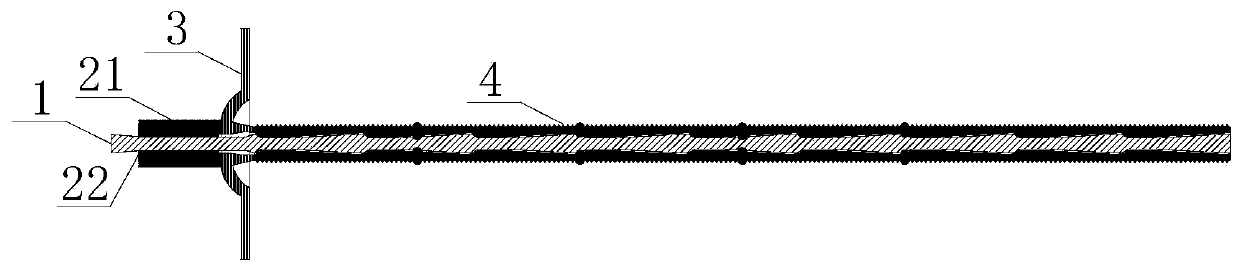
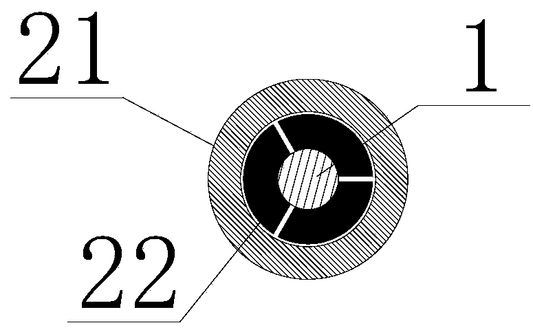
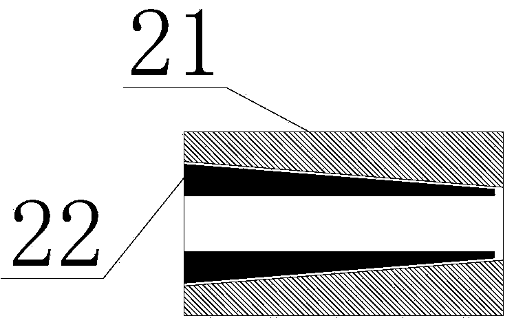
[0047] Such as figure 1 As shown, the high-stress impact ground pressure roadway bolt of the present invention includes a nodular bolt body 1, a bolt tail lock, a force transmission tray 3 and a sleeve 4;

[0048] The nodular anchor rod body 1 is provided with protrusions at intervals, and the protrusions are spherical protrusions or spindle-shaped protrusions; the tail end of the nodular anchor rod body 1 is provided with threads, and the threads are sequentially provided with a force transmission tray 3 and A bolt tail lock, the nodular anchor rod body 1 is provided with a sleeve 4, the sleeve 4 is a metal tube with a through-slit in the axial direction, the outside of the metal tube is provided with fine threads, and the inside of the metal tube is provided with a nodular The protrusion on the anchor rod body 1 is a concave structure that matches the pr...


PUM


Abstract

The invention provides a high-stress impact burst roadway anchor rod, a design method and a work method. The anchor rod is suitable for being used under a coal mine. The anchor rod comprises a joint-like anchor rod body, an anchor rod tail lock, a force transmitting tray and a sleeve. Protrusions are arranged on the joint-like anchor rod body at intervals. A thread is arranged at the tail end of the joint-like anchor rod body. The force transmitting tray and the anchor rod tail lock are sequentially arranged on the thread. The sleeve is arranged outside the joint-like anchor rod body. A metalpipe provided with a penetration seam in the axial direction is adopted as the sleeve. A fine thread is arranged on the outer side of the metal pipe. An inner concave structure matched with the protrusions on the joint-like anchor rod body is arranged in the metal pipe. The anchor rod has the advantages that anchoring force is high, pre-tightening force is high, and the overall anchoring effect isnot influenced by local breakage, and the anchor rod can effectively avoid the problems that the anchoring condition of a current common anchor rod is rigorous, the whole loses efficacy easily due tolocal breakage, the allowable deformation amount is small, and the anchor rod cannot adapt to high stress, large deformation, strong impact dynamic pressure and rock crushing engineering environments.

Description

technical field [0001] The invention relates to a roadway anchor rod for high stress impact rock pressure, a design method and a working method, and is especially suitable for a roadway anchor rod for high stress impact rock pressure used in coal mine underground roadways, a design method and a working method. Background technique [0002] Anchor is an important supporting material in the fields of mining engineering, hydropower engineering, slope engineering and underground engineering. At present, there are three main ways to generate the anchoring force of anchor bolts: through the chemical bonding of resin anchoring agents, the stretching and expansion of inverted wedge structures, or friction. The common anchors mainly include resin anchored rebar anchors, round steel Twist head bolts, mechanical inverted wedge bolts, expansion shell bolts, glass fiber reinforced plastic bolts, etc. There are mainly the following disadvantages: [0003] Resin coil anchor bolts have hi...

Claims


Application Information

Patent Timeline
Patent Type & Authority Applications(China)
IPC IPC(8): E21D21/00E21D20/02E02D5/74G06F17/50
CPCE21D21/00E21D21/0026E21D20/003E21D20/025E02D5/74
Inventor 孟波靖洪文杨圣奇齐燕军王迎超黄彦华方尧
Owner CHINA UNIV OF MINING & TECH
Why Eureka
Try Eureka