Waste gas cleaning treatment device for dyeing and finishing setting machine and operation method of waste gas cleaning treatment device

A technology of cleaning treatment and setting machine, which is applied in the direction of cleaning methods and utensils, separation methods, chemical instruments and methods, etc., can solve the problems of incomplete reaction, inconvenient recycling, waste of solution, etc., and achieve long-term reaction, convenient use, keep clean effect

Inactive Publication Date: 2019-12-20
杭州新融方科技有限公司
View PDF0 Cites 0 Cited by
  • Summary
  • Abstract
  • Description
  • Claims
  • Application Information

AI Technical Summary

Problems solved by technology

[0005] Aiming at the deficiencies of the prior art, the present invention provides a dyeing and finishing machine exhaust gas cleaning treatment device and its operation method, which solves the problem that the existing exhaust gas treatment devices have a large space, and the reaction time between the exhaust gas and the solution is short and the reaction time is relatively short. Incomplete, at the same time, the method of exhausting the exhaust gas into the solution will make the overall solution turbid, and if the solution is not completely reacted, it is not easy to recycle, and some solutions will be wasted

Method used


Image

  • Waste gas cleaning treatment device for dyeing and finishing setting machine and operation method of waste gas cleaning treatment device
  • Waste gas cleaning treatment device for dyeing and finishing setting machine and operation method of waste gas cleaning treatment device
  • Waste gas cleaning treatment device for dyeing and finishing setting machine and operation method of waste gas cleaning treatment device

Examples


Embodiment Construction

[0034] The following will clearly and completely describe the technical solutions in the embodiments of the present invention with reference to the accompanying drawings in the embodiments of the present invention. Obviously, the described embodiments are only some, not all, embodiments of the present invention. Based on the embodiments of the present invention, all other embodiments obtained by persons of ordinary skill in the art without making creative efforts belong to the protection scope of the present invention.

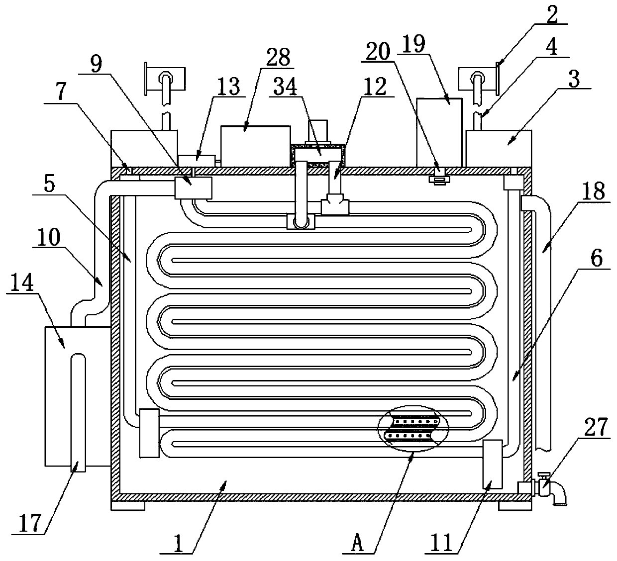
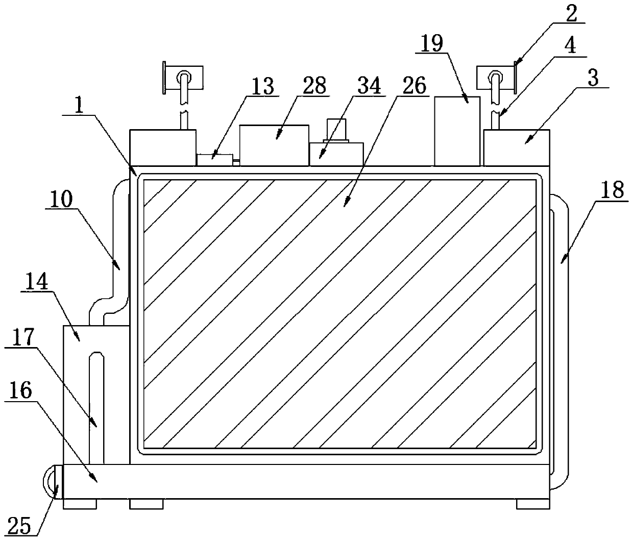
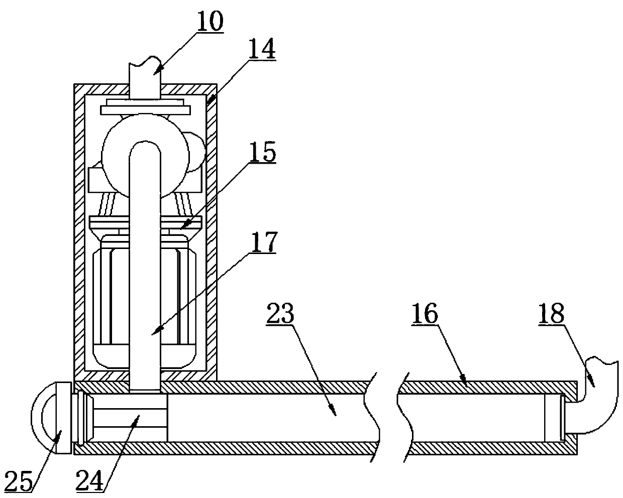
[0035] see Figure 1-7 , the embodiment of the present invention provides a technical solution: a dyeing and finishing machine exhaust gas cleaning treatment device, comprising a purification box 1 and an exhaust gas extraction box 2, the bottom of the left side of the purification box 1 is fixedly connected to an organic case 14, and the interior of the case 14 is fixed A water pump 15 is connected, and the bottom end of the suction pipe 10 runs through the p...


PUM


Abstract

The invention discloses a waste gas cleaning treatment device for a dyeing and finishing setting machine, wherein the waste gas cleaning treatment device comprises a purification box and a waste gas extraction box; exhaust fans are fixedly connected to the left side and the right side of the top of the purification box. The invention relates to the technical field of exhaust gas treatment. According to the waste gas cleaning treatment device for the dyeing and finishing setting machine and an operation method of the waste gas cleaning treatment device. Harmful waste gas can be directly exhausted into a first U-shaped pipe and a second U-shaped pipe through a gas outlet pipe; with use of winding tracks of the first U-shaped pipe and the second U-shaped pipe, the flowing time of the waste gas in a solution is greatly prolonged, thorough purification is maintained, and the occupied space is relatively small; meanwhile, after a solution in the first U-shaped pipe and the second U-shaped pipe becomes turbid, the solution is directly discharged and treated, and the solution can be automatically supplemented from the purification box through an automatic water supplementing pipe; meanwhile, the solution is divided into an inner layer and an outer layer through the first U-shaped pipe and the second U-shaped pipe, the divided solutions do not interfere with each other, residual relatively clean solution in the purification box can be still recovered after waste gas treatment is finished, and the cost is reduced.

Description

technical field [0001] The invention relates to the technical field of waste gas treatment, in particular to a device for cleaning waste gas of a dyeing and finishing machine and an operation method thereof. Background technique [0002] Exhaust gas purification mainly refers to the treatment of industrial waste gas such as dust particles, flue gas, odorous gas, and toxic and harmful gases generated in industrial places. Common exhaust gas purification includes factory smoke and dust exhaust gas purification, workshop dust exhaust gas purification, organic waste gas purification, Waste gas odor purification, acid-base waste gas purification, chemical waste gas purification, etc. The waste gas emitted by industrial production often has harmful effects on the environment and human health. Before being discharged into the atmosphere, purification measures should be taken to make it meet the requirements of waste gas emission standards. This process is called exhaust gas cleanin...

Claims


Application Information

Patent Timeline
Patent Type & Authority Applications(China)
IPC IPC(8): B01D53/78B01D53/40B01D46/00B01D46/24B01D46/30B08B15/00
CPCB01D53/78B01D53/40B01D46/24B01D46/30B08B15/00B01D46/62
Inventor 管晟琦管凯华
Owner 杭州新融方科技有限公司
Why Eureka
Try Eureka