An ultrasonic cleaning machine for auto parts
A kind of auto parts, ultrasonic technology, applied in the field of parts cleaning, can solve the problems of complicated installation and disassembly steps, single function, and reduced cleaning efficiency, etc., and achieve the effect of fast storage and easy reuse
- Summary
- Abstract
- Description
- Claims
- Application Information
AI Technical Summary
Problems solved by technology
Method used
Image
Examples
Embodiment 1
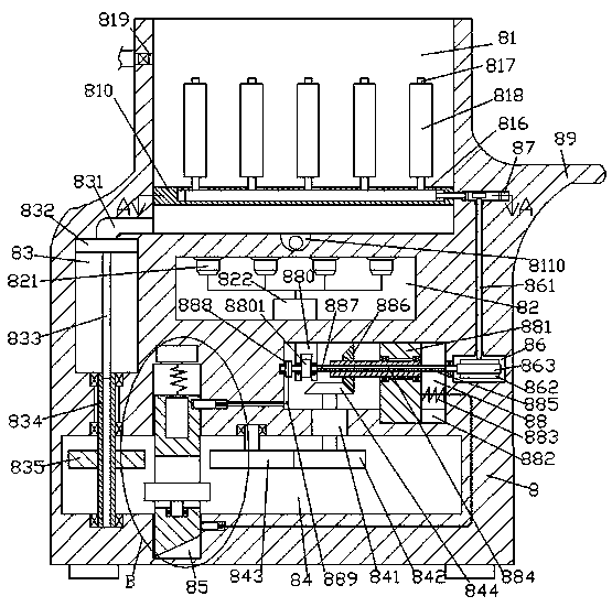
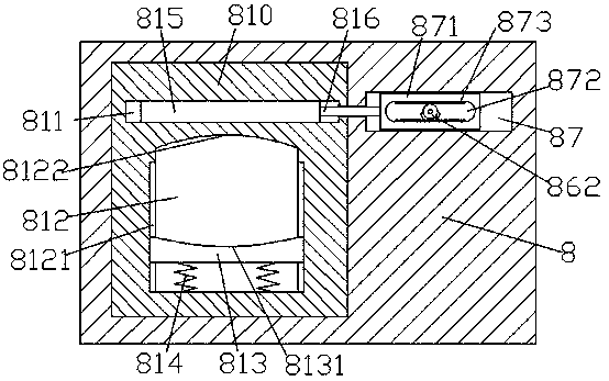
[0027] When cleaning is required, the parts to be cleaned are first installed in the clamping groove 812, so that the parts and the cleaning brush 818 are in contact with each other, and then the cleaning agent liquid supply valve 819 is opened to allow the cleaning liquid to enter the cleaning tank 81 Then, the ultrasonic transducer 821 is controlled by the ultrasonic generator 822 to generate ultrasonic waves. At the same time, the driving motor 841 drives the first bevel gear 844 to rotate, and then the first bevel gear 844 drives the second bevel gear 886 and the inner key rotary sleeve 884 Rotate, at this time, the second key shaft 887 and the first key shaft 885 are driven by the inner key rotating sleeve 884 to rotate, because the left side of the second key shaft 887 is provided with a one-way clutch 8801, at this time, the take-up wheel 888 is at rest At the same time, the rotation of the first key shaft 885 drives the worm 863 and the worm wheel 862 to rotate, and the...
Embodiment 2
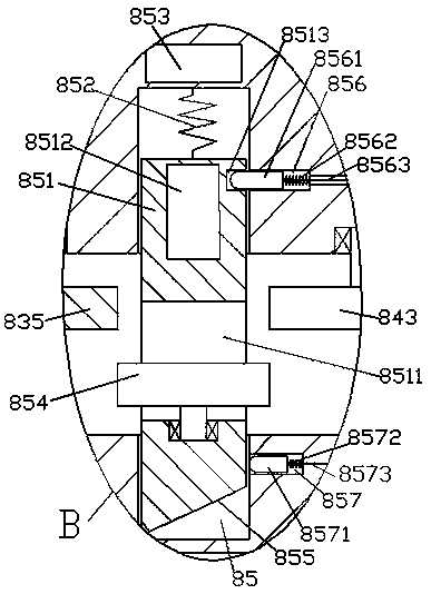
[0029]After clearing is finished, by controlling the drive motor 841 to rotate in reverse, then realize that the first bevel gear 844 drives the second bevel gear 886 and the inner key rotating sleeve 884 to rotate in reverse. At this time, the inner key rotating sleeve 884 drives the second The key shaft 887 and the first key shaft 885 rotate in the opposite direction, and the one-way clutch 8801 on the left side of the second key shaft 887 drives the take-up wheel 888 to rotate, and then the take-up wheel 888 drives the first pulley through the first pull cord 8563. The pin 8561 overcomes the pressing force of the third spring 8562, and makes the first sliding pin 8561 slide toward the right side in the first sliding pin groove 856 until the first sliding pin 8561 is completely disengaged from the connecting groove 8513. At this time, the linkage slider 851 is pulled by the tension spring 852, so that the linkage slider 851 slides to the top position in the linkage slide cavi...
Embodiment 3
[0031] When it is necessary to discharge the cleaning waste liquid, make the piston slider 832 located at the top position in the liquid storage chamber 83, then open the liquid discharge valve 8110, and then power on the electromagnetic coil device 853, and then make the electromagnetic coil device 853 and the magnetic block 8512 generates a repulsive force, and then the linkage slider 851 overcomes the pressing force of the tension spring 852 and slides downward. At this time, the inclined surface 855 at the bottom end of the linkage slider 851 abuts against each other, so that the second sliding pin 8571 overcomes the fourth spring 8572 The pressing force of the second slide pin is retracted into the second sliding pin groove 857, and the second pull cord 8573 is in a relaxed state again. Since the horizontal sliding block 881 is subjected to the pressing force of the second spring 883, the horizontal sliding block 881 is then slid to the horizontal slide groove. The leftmos...
PUM
 Abstract
Description
Claims
Application Information
 - R&D
- Intellectual Property
- Life Sciences
- Materials
- Tech Scout
- Unparalleled Data Quality
- Higher Quality Content
- 60% Fewer Hallucinations
Browse by: Latest US Patents, China's latest patents, Technical Efficacy Thesaurus, Application Domain, Technology Topic, Popular Technical Reports.
© 2025 PatSnap. All rights reserved.Legal|Privacy policy|Modern Slavery Act Transparency Statement|Sitemap|About US| Contact US: help@patsnap.com


