

Method for online monitoring milling cutter defects
A milling and cutting tool technology, applied in the direction of manufacturing tools, metal processing equipment, metal processing machinery parts, etc., can solve the problems of low processing efficiency, high operator skill requirements, missing milling tools, etc., to improve processing efficiency, monitor The effect is obvious and the effect of reducing the processing loss
- Summary
- Abstract
- Description
- Claims
- Application Information
AI Technical Summary
Problems solved by technology
Method used
Image

Examples
Embodiment 1
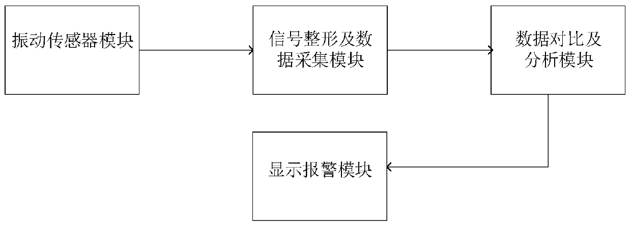
[0033] This embodiment discloses a method for online monitoring of milling tool defects, see figure 1 , including the following steps:
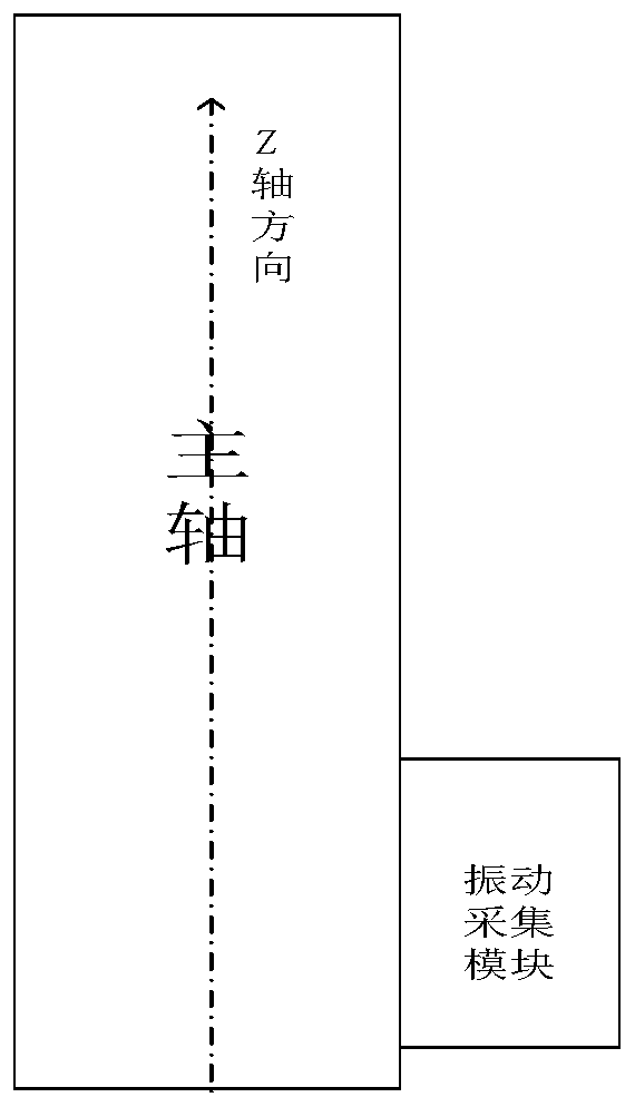
[0034] 1) see figure 2 , establish a three-dimensional space coordinate system oxyz with the machine tool spindle as the center. Wherein, the z axis is located on the axis of the machine tool spindle, and the x and y axes are respectively perpendicular to the z axis. Install the vibration sensor module on the machine tool spindle, start the machine tool spindle, and debug the vibration sensor module to ensure that the signals in the x, y, and z directions meet the requirements.
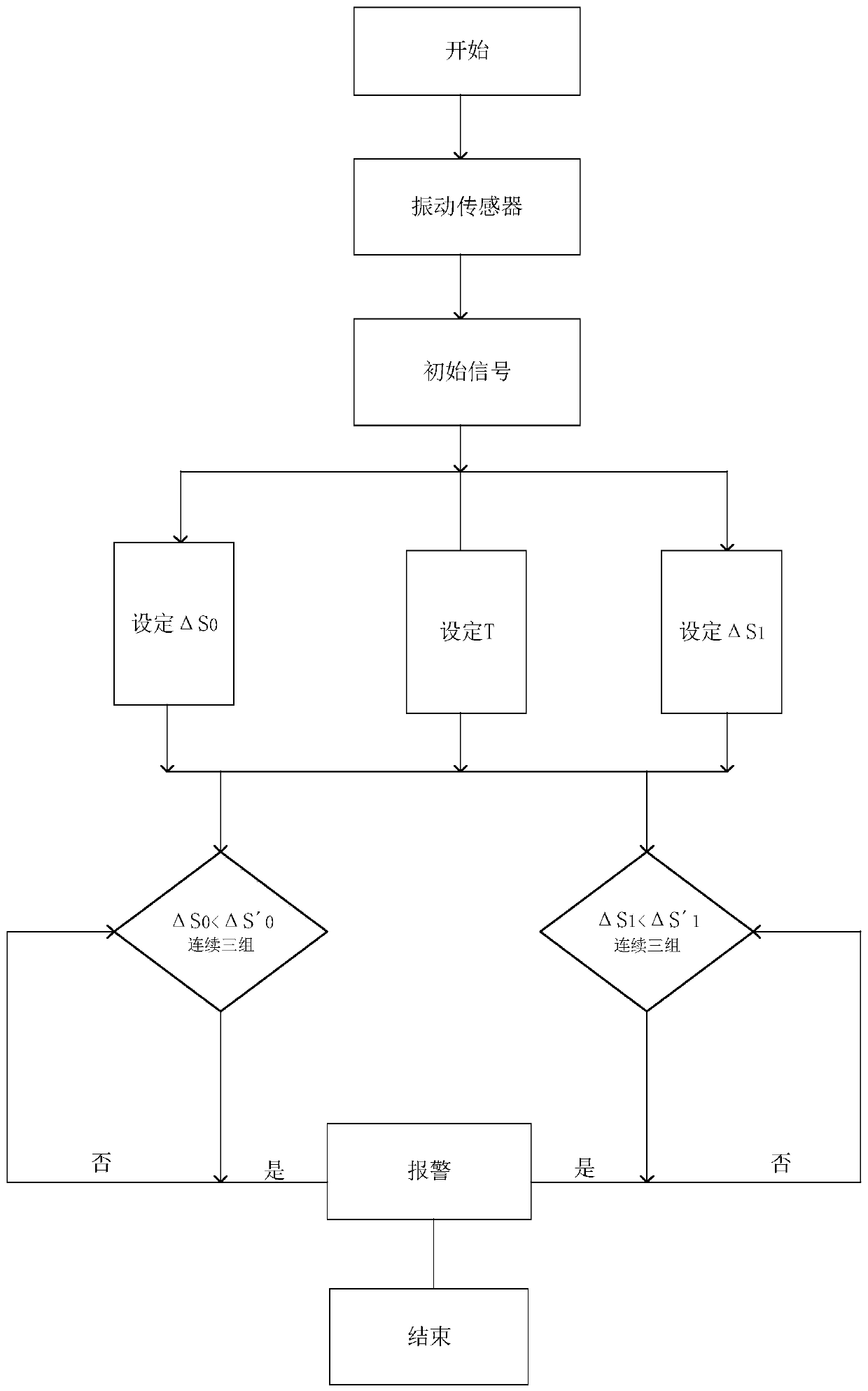
[0035] 2) see image 3 , initial sample data collection. specifically,
[0036] 2.1) Take one revolution of the main shaft as a cycle T 0 .
[0037] 2.2) In this embodiment, the number of blades on the cutter head is 4, and the blade numbers are 1, 2, 3, and 4 respectively. When the 4 blades on the cutter head enter normal milling, the vibration sensor module...
Embodiment 2
[0052] This embodiment discloses a relatively basic implementation method, a method for online monitoring of milling tool defects, see figure 1 , including the following steps:
[0053] 1) see figure 2 , establish a three-dimensional space coordinate system oxyz with the machine tool spindle as the center. Wherein, the z axis is located on the axis of the machine tool spindle, and the x and y axes are respectively perpendicular to the z axis. Install the vibration sensor module on the machine tool spindle, start the machine tool spindle, and debug the vibration sensor module to ensure that the signals in the x, y, and z directions meet the requirements.
[0054] 2) see image 3 , initial sample data collection. specifically,
[0055] 2.1) Take one revolution of the main shaft as a cycle T 0 .
[0056] 2.2) In this embodiment, the number of blades on the cutter head is 4, and the blade numbers are 1, 2, 3, and 4 respectively. When the 4 blades on the cutter head enter n...
Embodiment 3
[0069] The main steps of this embodiment are the same as those of Embodiment 2. Further, in step 7), if the subsequent two consecutive sets of data do not satisfy the Then it can be ruled out that the phenomenon of increased local vibration caused by casting or forging defects during tool cutting, rather than increased vibration caused by tool defects, proceeds to step 8).
[0070] Example 3:
[0071] The main steps of this embodiment are the same as those of Embodiment 2, and further, step 9) is also included. If the display alarm module does not issue an alarm during the entire processing process, the data comparison and analysis module records the processing parameters of the entire process, and the collected strong vibration cutting Wave data analysis and processing obtains the cutting wave area and saves it as a signal comparison sample material for later processing of the same workpiece.
PUM
 Abstract
Description
Claims
Application Information