Novel mortar spreading machine

A new type of grouting technology, applied in the direction of architecture and building construction, can solve the problems of high proficiency requirements, difficulty in achieving accuracy, and few auxiliary equipment, etc., and achieve simple overall structure, good detachability, and stability good sex effect

Inactive Publication Date: 2019-12-20
CENTRAL SOUTH UNIVERSITY OF FORESTRY AND TECHNOLOGY
View PDF6 Cites 3 Cited by
  • Summary
  • Abstract
  • Description
  • Claims
  • Application Information

AI Technical Summary

Problems solved by technology

[0006] The inventor of this patent application combined with practical operations found that manual grouting requires a high level of proficiency for the master worker, and the flatness of the bricks depends entirely on the feeling of the master worker, and it is difficult to achieve accuracy. In addition, manual operation is time-consuming and laborious, and it is difficult to achieve efficient construction.
Although the existing spraying machine can complete the grouting work, the density and quality of the sprayed grout outlet are not uniform, and there are many auxiliary equipments, so it is difficult to adapt to small-scale construction.
[0007] To sum up, there is currently a lack of a new type of coating with high slurry distribution efficiency, more uniform slurry distribution, convenient slurry addition, adjustable slurry width and height, simplified structure, less auxiliary equipment, and better adaptability to small construction sites. pulp machine

Method used


Image

  • Novel mortar spreading machine
  • Novel mortar spreading machine
  • Novel mortar spreading machine

Examples


Embodiment Construction

[0025] The present invention will be described in further detail below in conjunction with the accompanying drawings.

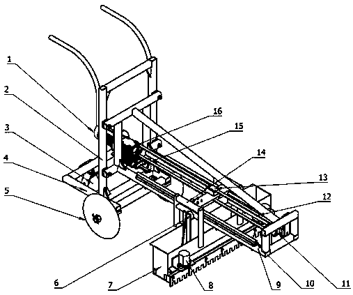
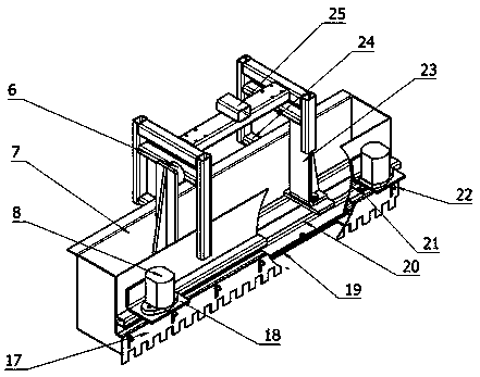
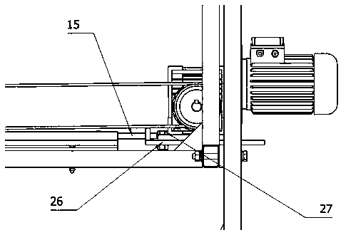
[0026] combined with figure 1 to attach image 3 , a new type of grouting machine, it includes a bracket assembly, a guide rail 10 is installed on the bracket assembly, a distribution bucket frame 14 is slidably fitted on the guide rail 10, and a distribution bucket frame 14 is connected to drive it along the guide rail. 10 reciprocating driving device, the bottom of the distribution bucket frame 14 is connected with a hopper mechanism for automatic slurry discharge, the hopper mechanism includes a distribution hopper 7 and a pressing plate 19, the upper part of the distribution hopper 7 is open, and the lower part is provided There is a discharge hole, and a scraper 17 is installed below the discharge hole. The scraper 17 is provided with comb teeth, and the pressing plate 19 is arranged in the distribution hopper 7. The upper opening area of ​​each is the...


PUM


Abstract

The invention discloses a novel mortar spreading machine. The novel mortar spreading machine is more uniform in mortar spreading and achieves convenient mortar feeding, the mortar spreading width andheight can be adjusted, the structure is simple and compact, the number of auxiliary devices is small, and the novel mortar spreading machine has better adaptability to a small-sized construction site. The novel mortar spreading machine comprises a support assembly. A guide rail is installed on the support assembly. A material distribution hopper rack is arranged on the guide rail in a sliding fitmanner and connected with a drive device used for driving the material distribution hopper rack to conduct reciprocating motion along the guide rail. The lower side of the material distribution hopper rack is connected with a material hopper mechanism achieving automatic mortar discharge. The material hopper mechanism comprises a material distribution hopper and a pressing plate. The upper part of the material distribution hopper is open, and the lower part of the material distribution hopper is provided with a row of material discharge holes. A screed is installed below the material discharge holes. The screed is provided with comb teeth. The pressing plate is arranged in the material distribution hopper. The size of the plate face of the pressing plate is identical with the area of theopening on the upper part of the material distribution hopper. The pressing plate is used for pressing cement mortar in the material distribution hopper to the material discharge holes to be discharged. The pressing plate is connected with a locating mechanism controlling the position of the pressing plate.

Description

technical field [0001] The invention relates to a machine for pre-distributing grout when laying tiles in the construction industry, in particular to a novel grouting machine. Background technique [0002] In the process of building construction, it is often necessary to use a large number of tiles. When laying tiles, it is necessary to lay out slurry (cement mortar) in advance as an adhesive between bricks and the ground or wall. This process is commonly known as plastering. In the construction industry, plastering is the foundation of brick laying and wall masonry, and the quality of cement mortar application directly determines the quality of construction. [0003] The existing pulp distribution methods are roughly divided into the following two types: [0004] (1) Manual grouting, manual grouting refers to placing the grout at a designated position, manually scraping it with putty, and then placing the tiles on the grout, and then beating to make the tiles flush with th...

Claims


Application Information

Patent Timeline
Patent Type & Authority Applications(China)
IPC IPC(8): E04F21/08
CPCE04F21/08
Inventor 喻秋良王树国李立君
Owner CENTRAL SOUTH UNIVERSITY OF FORESTRY AND TECHNOLOGY
Why Eureka
Try Eureka